Download
1 / 23
260 likes | 274 Views
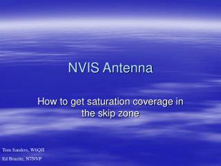
Near Vertical Incidence Sky Wave (NVIS) Propagation. Marc C. Tarplee, Ph.D. NCE N4UFP. Background. Near Vertical Incidence Sky Wave (NVIS) propagation provides local and regional coverage on the lower HF bands. NVIS is not new. German army experimented with NVIS during WW II

E N D
Near Vertical Incidence Sky Wave (NVIS) Propagation Marc C. Tarplee, Ph.D. NCE N4UFP
Background • Near Vertical Incidence Sky Wave (NVIS) propagation provides local and regional coverage on the lower HF bands. • NVIS is not new. • German army experimented with NVIS during WW II • US military personnel used NVIS in Vietnam. • Many amateurs have used NVIS on 80 and 160m without knowing it.
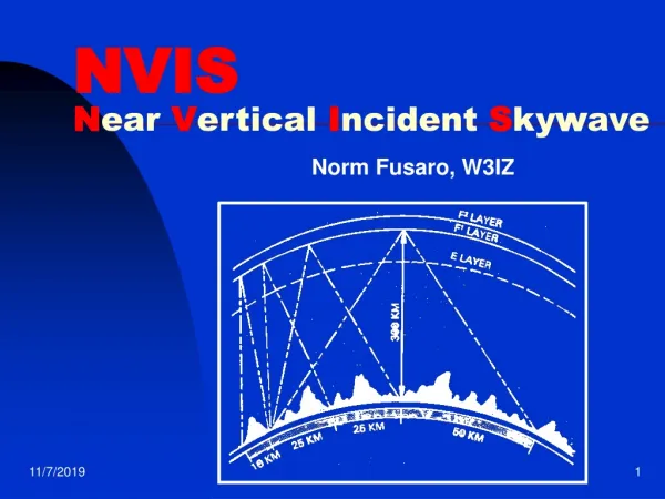
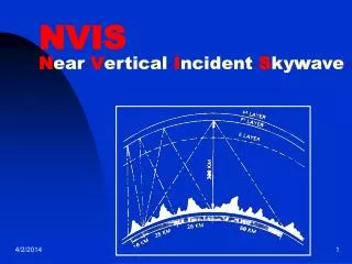
How NVIS works • RF is launched at a high elevation angle (> 70 degrees). • If the frequency of the RF is below the critical frequency, it will be refracted back towards the earth’s surface. • Because the RF is launched at a nearly vertical angle, it returns to earth close (1 – 300 mi) to the transmitter • Attenuation on NVIS paths is less than DX paths because the RF takes the shortest possible trip through the ionosphere’s highly absorbing D layer
How NVIS works • In order for the NVIS signal to be returned to the earth’s surface, its frequency must be less than the critical frequency of the F-layer • During daytime, the critical frequency is approximately 5 to 15 MHz. After sunset, the critical frequency drops throughout the night, reaching a low of 1 to 5 MHz just before dawn. • It is desirable to use frequencies just below the critical frequency to minimize signal absorption by the D-layer
Band Selection for NVIS • Periods of high solar activity • Daytime - 60, 40 and 30 m • Nighttime – 60 and 80 m • Periods of low solar activity • Daytime - 80, 60 or 40m • Nighttime - 80 or 160 m
Advantages of NVIS • Elimination of the Skip Zone • NVIS provides good coverage between the outer limit of ground wave propagation (25 miles) and the inner limit of normal sky wave return (300 miles). • Noise Reduction • NVIS antennas “look” directly into outer space and most astronomical objects are not powerful emitters in the lower HF region • Terrestrial noise sources are not in the field of view of the antenna and do not contribute significantly to received noise.
NVIS Applications • Emergency Communications • Reliable NVIS communications are possible out to distances of approximately 300 miles • Small number of NVIS stations are required to provide a statewide network. • Amateurs can quickly establish communications using NVIS after a natural disaster because NVIS uses readily available HF equipment and simple antennas. • NVIS is adaptable. CW, SSB and various HF digital modes such as PSK-31 all can be used with NVIS • Traffic Nets • NVIS eliminates the skip zone, permitting smoother traffic handling
NVIS Operation • Prior planning is important - an NVIS net must have frequency agility. • The Net Manager and Net Control Stations should determine the operating frequencies that will be used at various times of the day • Procedures for frequency hopping must be agreed on beforehand, so that stations are not lost as the net moves from band to band • Practice before the emergency is mandatory!
Sample NVIS Net Frequency Plan • SC Region 2 NVIS Net Frequency Plan • Winter Plan, SSB Nets • Local Time of Net Operating Frequency (1-5) • 0001 – 0800 Primary: 3.996 MHz Alternate: 1.976 MHz • 0801 – 1600 Primary: 7.285 MHz Alternate: 5.40350 MHz • 1601 – 2000 Primary: 5.40350 MHz Alternate: 3.996 MHz • 2001 – 2400 Primary: 3.996 MHz Alternate: 1.976 MHz • Summer Plan, SSB Nets • Local Time of Net Operating Frequency (1-5) • 0001 – 0800 Primary: 3.996 MHz Alternate: 1.976 MHz • 0801 – 1600 Primary: 5.40350 MHz Alternate: 3.996 MHz • 1601 – 2400 Primary: 3.996 MHz Alternate: 1.976 MHz
Sample NVIS Net Frequency Plan • SC Region 2 NVIS Net Frequency Plan • Operating Notes • If primary frequency cannot support NVIS, the net will move to the alternate frequency for the time period in which the net is operating. If the alternate frequency cannot support NVIS, the net will move to the alternate frequency of the next later time period, if it is lower than the current alternate frequency. If the alternate frequency of the later time period is not lower, use the alternate frequency from the adjacent earlier time period, if it is lower. If a lower alternate frequency cannot be found, the net must be moved to VHF. • Band changes will occur at quarter hour intervals. • All operating frequencies, other than those in the 60m band, may vary by +/- 10 KHz to avoid interference. • Output power on 60m must be limited to 50 W PEP. • Only USB is allowed on 60 m
Assembling an NVIS Station • A standard 100W HF transceiver will work just fine for NVIS • The key element of an NVIS station is the antenna. • It must be designed to radiate at very high takeoff angles. • Generally, existing amateur antenna systems, with the exception of most 160 m dipoles, do not radiate in the proper direction for NVIS operation
NVIS Dipoles • Mounted at a height between 0.1 and 0.2. • Takeoff angle is 90 deg. • Antenna height below 0.1 can cause problems • Rapid decrease in gain below 0.1 (3 dB loss at 0.05 ) • Decrease in feed point impedance below 0.1 • Antenna may be erected as an inverted-vee with only one support • Max height should be less than 0.25 • People should be kept away from the ends of the antenna
Band Dipole Length 160 (1.9 MHz) 250 ft 80 (3.9 MHz) 121 ft 10 in 60 (5.37 MHz) 88 ft 5 in 40 (7.2 MHz) 65 ft 11 in Construction of NVIS Dipoles • Use copper or aluminum wire • #14 THHN stranded wire – available in 500-foot rolls for ~ $15. • #17 Aluminum fence wire - available in quarter-mile roles for ~ $14, • NVIS dipole lengths
Elevation Radiation pattern of an 80m NVIS dipole 12.5 ft above ground Multiband Operation with NVIS Dipoles • Dipole should be fed with ladder line • Antenna must be less than 0.2 high at the highest operating frequency. • Operation is possible from 0.5 to approximately 3.0 times the fundamental frequency
NVIS Loop Antennas • 1λ loop antenna can also be used for NVIS operation • Two possible arrangements • It can be mounted horizontally close to the ground and the feed point can be anyplace along the loop. 3 supports needed • It can be mounted vertically with the bottom wire close to ground and fed to produce horizontally polarized RF. 1 support needed
Horizontal NVIS Loop • Should be at a height of 0.1 to < 0.2, • Gain drops off quickly at heights below 0.1. • Input impedance is 70 – 140 ohms over average ground.
Elevation Radiation Pattern of an 80m Horizontal NVIS loop 12.5 ft above ground Multiband Operation with a Horizontal NVIS Loop • The loop should be fed with ladder line • The loop must be less than 0.2 high at the highest operating frequency. • Operation is possible from 0.5 to approximately 1.6 times the fundamental frequency
Vertical NVIS Loop • Generally a delta loop is mounted on a single support • Apex height is approximately 0.25 high, • Bottom wire raised approximately 0.1 above the ground. • Takeoff angle is 90 degrees • Input Impedance is 100- 140 ohms
Radiation Pattern of an 80 m Vertical NVIS Loop 12.5 ft above ground Multiband Operation with a Vertical NVIS Loop • The loop should be fed with ladder line • The loop must be less than 0.2 high at the highest operating frequency. • Operation is possible from 0.5 to approximately 1.8 times the fundamental frequency
Mobile/Portable Antennas for NVIS • Inverted L made by bending a mobile whip antenna over the roof of a vehicle. • Short dipole made by combining 2 loaded fiberglass whip antennas designed for vehicle use • Any metal object that is parallel to the ground and not more than 10 – 15 feet above it. ( example – residential gutter system) • A dipole laying on the ground • Improved SNR possible in NVIS operation offsets high losses in a ground mounted antenna.
Summary • NVIS is a mode that many amateurs have used without recognizing it for what it is. • It requires no special equipment, only special antennas. • NVIS can provide regional coverage with high SNR provided that good operating procedure is used. • NVIS is an operating mode that should be part of every EC’s emergency communications “tool kit”.