Download
1 / 15
150 likes | 173 Views
Chapter 6 System Integration and Performance. System Bus Bus Parallel communications lines that connect two or more devices System Bus Connects the CPU with the other components Peripheral Devices Devices other than CPU and Primary Storage (main memory) Data Bus

E N D
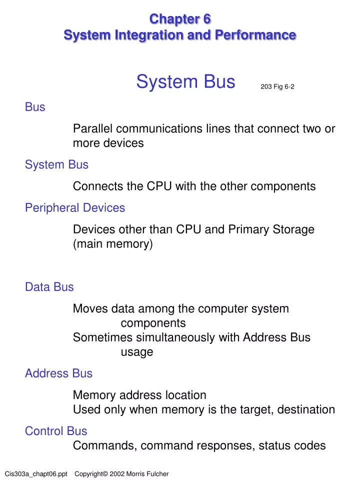
Chapter 6System Integration and Performance System Bus Bus Parallel communications lines that connect two or more devices System Bus Connects the CPU with the other components Peripheral Devices Devices other than CPU and Primary Storage (main memory) Data Bus Moves data among the computer system components Sometimes simultaneously with Address Bus usage Address Bus Memory address location Used only when memory is the target, destination Control Bus Commands, command responses, status codes 203 Fig 6-2
Address Bus Control Bus Data Bus Primary Storage (memory) CPU Secondary Storage I/O Units System Bus Control UnitALURegisters Main Memory Hard Disk PrintersScannersFloppy diskCDsDVDsMouseMonitor
Measurements Milliseconds: thousandths of a second 1/1,000 second = .001 Microseconds: millionths of a second 1/1,000,000 second = .000001 Nanoseconds: billionths of a second 1/1,000,000,000 second = .000000001
System Bus Bus Clock Carried on one or more of the Control Bus lines Megahertz (MHz): the frequency of the clock pulses Coordinates all I/O activity Each pulse marks the beginning of a new opportunity (period) for an I/O activity Bus Cycle The time interval from one clock pulse to the next The amount of time of one (1) cycle Ex. Clock Rate = 133 MHz 133,000,000 pulses (cycles) per second 1 ---------------- = .000000007518 seconds 133,000,000 .000000007518 seconds = 7.518 nanoseconds 203
System Bus Considerations Bus clock rate is below maximum due to: Noise Interference Time required for peripheral device interface circuits to set up Slower bus clock rates Increase peripheral device reliability Acceptable cost levels Data Transfer Rate (bus capacity) Amount of data that can be transferred in one second Data Transfer Unit Amount of data a computer transfers at one time Data Transfer Unit X Clock Rate 64 bits X 100 MHz 8 bytes X 100,000,000 Hz 800,000,000 bytes per second 204
Bus Protocol Protocol manners, etiquette , code of behavior , practice set of rules, modus operandi, method Governs Transmitting/receiving format Content of information Timing (along with the system clock) Data Memory addresses Control messages Data Transfer Rate impacts Control signals consume clock pulses Less pulses for transferring data Handshaking: page 205 Efficient bus protocols are complex thus costly Bus and peripherals Bus Master CPU Coordinates all communication between devices System performance reduced Bus Slave I/O devices use the bus via control by the CPU
Bus Protocol Performance Improvement Storage (memory) and I/O devices can communicate directly Two methods 1. Direct memory Access (DMA) DMA Controller Attaches bus to main memory Assumes role of Bus Master for memory and I/O device communications Handles transfers between memory and I/O devices Frees up CPU to continue processing by relieving the CPU responsibility for also controlling the bus(computers only do 1 thing at a time) 2. Multiple Master Bus Any I/O device acts as bus master for transfers to any other I/O device, not just memory. An arbitration unit determines which I/O device becomes master Complex and costly
Logical and Physical Access I/O Port A communications pathway from the computer to a peripheral A physical connection board and slot A logical connection Memory address Read and written to by a peripheral Controlled by a program (driver) I/O Port Driver CPU instruction set is simpler CPU does not have to understand each peripheral language Special bus circuitry is not required for each peripheral New peripherals may be added more easily Relieves CPU responsibility for knowing Storage capacity Data transfer rate Internal data coding methods Device is a storage or I/O 206
Device Controllers Device Controller Connects the device to the system bus Monitor the bus control lines Translate commands Data formats translated to/from CPU Command and status commands translated Perform conversions between logical and physical access commands Allow more than one physical device to be connected to the bus Implement the bus interface Implement access protocols Translate logical accesses into physical accesses Permit several devices to share access to the bus 208
Mainframe Channels I/O Channel or Channel A dedicated special-purpose computer Allows CPU to continue processing Controlled by the Channel Command Word (CCW) Channel Status Word (CSW)
SCSISmall Computer System Interface 211 Fig 6-6 Standard busses designed for secondary storage devices Connect up to 16 I/O devices Addressed 0 – 15 Control Bus control (commands) device status Data bus Data transmission Device identification Allows multiple devices to be bus master SCSI Controller Translation between system bus and SCSI bus
Interrupts 213 I/O Wait State CPU waiting for a device to complete a request No CPU cycles are being used to execute instructions Interrupt A signal from a device to gain the CPUs attention The CPU stores the interrupt in the Interrupt Register Interrupt Register Contains the Interrupt Code Interrupt Code Bus Port and peripheral device address CPU monitors the Interrupt Register Interrogates the IR at end of execution cycle If non-zero – current process is suspended and the CPU processes the interrupt Interrupt Handler service routines In main memory One for each possible interrupt
Stack Processing 215 A mechanism that allows a program to resume execution in exactly the same state (swapping registers) Stack An area of main memory that is accessed in a last-in, first-out (LIFO) method Is in main memory The last set of registers in the stack are the first out Push Placing the current registers into (onto) the stack Pop Retrieving the top (last) registers from the stack and placing them into the current registers Stack Overflow error Stack is full – all space allocated for stack memory is in use – no more Pushing is allowed Stack Pointer register Points to next empty address in the stack
Buffers and Caches 217 Improve computer system performance Main memory Buffers Small storage area in main memory Holds data in transit from one device to another Due to differences in Data transfer size Data transfer rate Data is temporary Data is automatically removed following use (transfer) Single direction data flow Cache Main memory Improve system performance Content is not automatically removed Data can be stored for future use Bi-directional data flow Requires intelligent management (software) Primary Storage Cache SRAM (fast but expensive) used as cache between main memory DRAM (slower and more inexpensive) 218 221 224
Compression Compression A technique to reduce the number of bits used to encode a data item (i.e. file) Removal of ‘waster’ or not used space Compression algorithm A mathematical compression technique implemented as a program Decompression algorithm Restores compressed data Lossless compression Decompressing results in exactly the same file that was compressed Accounting Programs Lossy compression The decompressed data is not exactly the same as the data that was compressed Audio Video Humans ‘fill in the blanks’ of what is missing Compression ratio The ratio of the size of the data before and after the compression