Download
1 / 24
240 likes | 364 Views
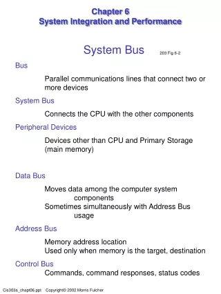
System Integration and Performance. System Bus. Connects the CPU with main memory and other system components. Each bus line can carry a single bit value during any bus transfer operation. Computer systems have THEE subsets of bus lines to carry specific types of information.

E N D
System Bus • Connects the CPU with main memory and other system components. • Each bus line can carry a single bit value during any bus transfer operation. • Computer systems have THEE subsets of bus lines to carry specific types of information. The data bus The address bus The control bus
Data bus moves data among computer system components. The number of lines is the same as the CPU word size. Address bus carries the bits of a memory address. Control bus carries commands, command responses, status codes, and similar messages.
Bus Clock • Timing reference for all attached devices. • The frequency of bus clock pulses is measured in megahertz. • Each clock pulse marks the start of a new opportunity to transmit data. • The time interval from one clock pulse to the next is called bus cycle. • Bus cycle can’t be shorter than the time required for an electrical signal to traverse the bus from end to end.
Data Transfer Rate • Rate at which data is transmitted through a medium or communication channel. bus capacity = data transfer unit * clock rate = 64 bits * 100 MHz = 8 bytes * 100,000,000 Hz = 800,000,000 bytes per second two ways to increase the maximum bus data transfer rate: - increase clock rate - increase the data transfer unit size
Bus Protocol • Governs the format, content, and timing of data, memory addresses, and control messages sent across the bus. • Efficient bus protocol consumes a minimal number of bus cycles, maximize bus for data transfers. But it is complex, increase the complexity and cost of the bus and all devices. • Prevents devices from interfering with one another. • A multiple master bus or DMA gives devices other than the CPU control of the bus, resulting in improved computer system performance.
Logical and Physical Access • CPU communicates with devices through I/O ports. To simplify the bus and the CPU instruction set, interaction with all devices is implemented with simple data movement instructions. CPU treats each device as if it is a storage device with a linear address space. • The device controller must translate access commands to the linear address space into whatever physical actions are necessary to perform the access.
Device Controllers • Perform a number of functions: - Implement the bus interface and access protocols Device controllers monitor the bus control lines for signals to devices and translate those signals into appropriate commands to the storage or I/O device. Similarly, data and status signals from the device are translated into appropriate control and data signals. A controller implements all bus interface functions for its attached device.
- Translate logical access into physical access. Device controllers know the physical details of the attached devices and issue specific instructions to the device based on that knowledge. E.g the device controller converts a logical access to a specific disk sector within a linear address space into a command to read from a specific head, track, and sector.
Permit several devices to share access to a bus connection This function is important because the number of physical I/O ports on the system bus is limited. Computer systems have several storage and I/O devices. Device controllers allow those devices to share a smaller number of bus connections. Most storage and I/O devices can’t sustain the system bus data transfer rate for extended periods. Sharing a single bus connection among multiple slower devices efficiently allocates the large communication capacity of a bus connection to many lower-capacity devices.
Mainframe Channel • A channel is an advanced type used in mainframe computer. Channels have greater data transfer capacity, a larger maximum number of attached devices, and greater variability in the types of devices that can be controlled compared with device controllers.
Interrupts • In a logical sense, an interrupt is a signal to the CPU that some event has occurred that requires the CPU to execute a specific program or process. • In a physical sense, an interrupt is an electrical signal generated by a device and then sent over the control bus.
Register in the control unit that stores an interrupt code received over the bus or generated by the central processing unit is called interrupt register. At the conclusion of each execution cycle, the control unit checks the interrupt register for a nonzero value. If one is present, the CPU suspends execution of the current process, reset the interrupt register to zero, and proceeds to process the interrupt. When the interrupt has been processed, the CPU resumes executing the suspended process.
Communication with devices through interrupts allows the CPU to do something useful while it’s waiting for an interrupt. • If the CPU is executing only a single process or program then there is no performance gain. If the CPU is sharing its processing cycles among many processes then the performance improvement can be substantial. • When one process requests data from a device the CPU suspends it and starts executing another process’s instructions. When an interrupt is received, indicating that the access is complete, the CPU retrieves the data, suspends the process it currently is executing, and returns to executing the process that requested the data.
Interrupt Handlers • To process each possible interrupt. • Each interrupt handler is a separate program stored in a separate part of primary storage. • In order to process an interrupt, the CPU must load the first instruction of the correct interrupt handler for execution.
When the CPU detects an interrupt, it executes a master interrupt handler program called the supervisor. The supervisor examines the interrupt code stored in the interrupt register and uses it as an index to the interrupt table. So the supervisor extracts the corresponding memory address and transfers control to the interrupt handler at that address.
Multiple Interrupts • Classified three categories: • I/O event – notify the OS that an access request has been processed and that data is ready for transfer. • Error condition - indicates errors that occur during normal processing. • Service request – used by the application programs to request OS services. An interrupt code is assigned to each service program, and an application program requests a service by placing the corresponding interrupt number in the interrupt register. The interrupt code is detected at the conclusion of the execution cycle, the requesting process is suspended, and the service program is executed.
Buffers and Caches • A buffer is a small storage area used to hold data in transit from one device to another. • Buffers resolve differences in data transfer rate or data transfer unit size. • A cache is a storage area to improve the system performance.
However a cache differs from a buffer in several important ways including: - data content is not automatically removed as it is used. - used for bi-directional data transfer - used only for storage devices accesses - larger than buffer - cache content must be managed intelligently When used for input, a cache gives more rapid access if the data being requested already is in the cache. The cache controller guesses what data the CPU will request next and loads that data into the cache before it are requested.
The Performance of writing to a cache • When the data is written to a cache, the confirmation signal is sent immediately to sending device, before the data is written to the storage device. • Sending a confirmation before data is written to the secondary storage device can improve program performance. • Performance improves because the program immediately can proceed with other processing tasks. • If the program is performing a series of write operations, performance improvements will cease as soon as the cache is full.
The Performance of a cache during read operation • Read accesses first are routed to the cache. • If the data is already in the cache then it is accessed from the receiving device. • Performance is improved because access to the cache is much faster than access to the storage device. • If the requested data is not in the cache, then it must be read from the storage device. • A performance is realized only if requested data already is waiting in the cache.
Compression • Reduces the number of bits used to encode a set of related data items. • A compression algorithm can be lossless or lossy. • Lossless compression – the result of compressing and then decompressing any data input is exactly the same as the original input. It is required in many applications, e.g, accounting records, executable programs, and most stored documents.
Lossy compression – the result of compressing and then decompressing a data input is different to the original input. It is applied in audio and video data. Decompression algorithm – restore compressed data to its original state. Data compression requires increased processing resources to implement the compression and decompression algorithms while reducing resources needed for data storage and communication.
Compression is used to reduce secondary storage requirements. • Data sent to the storage device is compressed before it’s written. • Data read from storage is decompressed before it’s sent to the requester. • Data is compressed as it enters the channel and then decompressed as it leaves the channel.