Download
1 / 43
430 likes | 530 Views
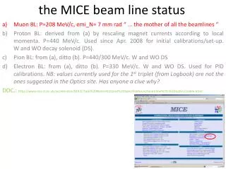
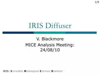
MICE beam diffuser. M. Apollonio , J. Cobb, P. Lau, W. Lau, J. Tacon, H. Witte, S. Yang - Univ. Oxford. circa 87 BC. outline. A bit of history … Choice of radius Choice of thickness Mechanics Control Conclusion/Plans. 0. Z=-6010 mm for the downstream face of the diffuser.

E N D
MICE beam diffuser M. Apollonio , J. Cobb, P. Lau, W. Lau, J. Tacon, H. Witte, S. Yang - Univ. Oxford circa 87 BC CM18, RAL, 14/6/2007
outline • A bit of history … • Choice of radius • Choice of thickness • Mechanics • Control • Conclusion/Plans CM18, RAL, 14/6/2007
0. Z=-6010 mm for the downstream face of the diffuser. (CR, CM14 Osaka - 2006) 1. radial size R as big as possible 2. thickness limited number of discs to fulfil MICE configurations 3. mechanics & control design still evolving a) new carousel wheel b) motors c) ideas for control (logic) CM18, RAL, 14/6/2007
radial size CM18, RAL, 14/6/2007
LEADING IDEA trying to exploit all the radial space (15 cm) within the envelope being compatible with mechanical constraints CM18, RAL, 14/6/2007
Muons selected on the overall channel ideal disc 7mm 15.5cm 7mm Emi inflation in single layer lead diffuser: 2.8 6.1 mm rad emi(after diff)=6 mm rad CM18, RAL, 14/6/2007
7mm 7mm 5cm 15.5cm 7mm Emi inflation with a single layer of lead (small radius): 2.8 5.3 mm rad CM18, RAL, 14/6/2007
a more realistic diffuser 7mm 7mm 5cm 15.5cm 7mm 7mm Emi inflation in a staggered lead diffuser: 2.8 6.1 mm rad fixed annulus movable disc + support CM18, RAL, 14/6/2007
emi(R)/emi(R=30 cm) single disc staggered discs Pz=148 MeV/c, emi=10mm rad, B=2.9 T Pz=209 MeV/c, emi=10mm rad, B=4 T Pz=267 MeV/c, emi=10mm rad, B=4 T Emittance bias as a function of R_diff (partial inflation) R_diff CM18, RAL, 14/6/2007
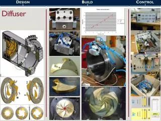
Proposal to accommodate many configurations STAGGERED/TAPERED with a fixed external annulus …just a sketch (see Peter/Joseph/Stephanie drawings) diffuser tracker envelope 1.5 to 15.5mm 30 cm 24 to 27 cm Supports (outer can/disc support): Al Pb diffuser disc and outer annulus 10 mm CM18, RAL, 14/6/2007
thickness choice CM18, RAL, 14/6/2007
How many configurations we need? want? … = 1.4 mm rad un-normalized CM18, RAL, 14/6/2007
… maybe 5 discs are enough (at least to begin with) Thinner disc: Pb Steel? MICE note in preparation CM18, RAL, 14/6/2007
mechanics CM18, RAL, 14/6/2007
automatic device with 3 main movements & accurate positioning • Carousel (revolving) • Discs (+/- 15 deg) • Catcher (linear motion through a threaded cylinder) CM18, RAL, 14/6/2007
diffuser disc on holder New design empty station encoder air motors hub CM18, RAL, 14/6/2007
P. Lau Motor A Motor C Disc 1 Disc 2 Motor B Dummy Disc Disc 3 Disc 5 Disc 5 CM18, RAL, 14/6/2007
To verify whether the lead is in the bayonet gear or not Motor A To identify which lead is at The center of the beam P. Lau CM18, RAL, 14/6/2007
EncoderReader Bayonet Gear; Turn 15° to clockwise to unlock and anti- Clockwise to lock Motor B to drive to turn the disc holder 15° clockwise & anti-clockwise P. Lau Encoder CM18, RAL, 14/6/2007
P. Lau Motor C This gear is to drive the diffuser catcher forward and backward CM18, RAL, 14/6/2007
MICE axis 5 optical sensors to check disc position (4) + disc presence (1) CM18, RAL, 14/6/2007
4 bit ~Gray code When this bit is 1 we sense the disc CM18, RAL, 14/6/2007
mS1 2 m-switches (check if disc at bottom of TH) 1 optical sensor (check if disc at top of TH) Pb disc + frame Pb external annulus catcher mS2 S. Yang OS CM18, RAL, 14/6/2007
OS: carousel and disc encoder OS: disc holder CM18, RAL, 14/6/2007
motors in the magnetic field can they work ? B (T) 0.32 T R (m) 0.53 T 0.61 T B>= 4T CM18, RAL, 14/6/2007 Z (m)
Air Motors • Must be non- magnetic • Acetal Body, SS shaft, Ceramic bearing. • The company does it is Dynatork • 10 to 12 weeks deliver time • The cost is around £1,000 excludes VAT for 3 off • Working pressure – 100 PSI • The maximum torque is 2.8 Nm • The speed is 200 rpm • No speed control • No positioning control • What problem we will tackle due to above parameter? • How to stop it? • Any accuracy concerns? CM18, RAL, 14/6/2007
For the Carousel • The total mass is about 70 kg • The moment of inertia is about 5.1 kg m² • To stop the carousel:- • To reduce the speed by introducing the gear box A with gear ratio 200:1, driving teeth ratio 3:1, total reduction is 600:1 • By use of the binary sensor to read the position of carousel. • By using the spring ball and dimple to guide the stop position of the carousel. • Use the lock pin to hold the carousel in place before the next motion CM18, RAL, 14/6/2007
For the 15° disc holder Drive by the air motor B; • To reduce the speed by introducing the gear box B with gear ratio 51:1, teeth driving ratio 7.77 :1, total reduction is 400:1 • By use of the Heidenhein 4000 series encoder to ensure the very high accuracy of positioning. CM18, RAL, 14/6/2007
For the diffuser plate transportation • To locate the lead disc; • To reduce the speed by introducing the gear box C with gear ratio 3:1 and the teeth driving ratio of 2.7:1, total reduction is 8.1:1 • Use RS- micro switch to detect the position of the lead disc at the bottom position. • Use RS reflective photo sensor to detect the top position of the lead disc. CM18, RAL, 14/6/2007
Epicyclic Gear Arrangement: J. Tacon Output Input For 1 rotation of shaft L shaft S rotates: ( 1 + NA / NS ) Gear Ratio: (1+42/14) = 4:1 with shaft S as the input. CM18, RAL, 14/6/2007
logic & control CM18, RAL, 14/6/2007
Diffuser Control Flow Chart:main cycle Start: go to Nf (mS1&&mS2) off? NB: need to know WHICH disc is in ! OS on? Which disc is in? Nd Nd = 0 OS on? Move C to position Nd STOP !!! ERROR Extract disc align disc holder: motor CW (+15 deg abs) Move catcher to bottom align disc holder: motor ACW (-15 deg abs) Move catcher to bottom Move C to position Nf Go to dummy station Move Catcher to top Insert disc Command: set disc-f for run mode Go to dummy station STOP CM18, RAL, 14/6/2007
START Diffuser Control Flow Chart: check discs insertedat the end of this cycle I should have a 5-element vector like (1,1,1,0,1) telling which station is empty. If the number of empty stations (Ne) is greater than 1 an error is produced which stops the system Ns=1 NT=0, Ne=0 GO TO position Ns Sense disc Record station (Ns: 0,1) If 0 Ne=Ne+1, Nd=Ns If 1 NT=NT+1 Ns=Ns+1 Ne<=1? Ns>=6 STOP !!! ERROR Go to dummy station CM18, RAL, 14/6/2007
START Diffuser Control Flow Chart: move C to position Nd • release BR-PIN Rotate CAROUSEL C.W. (till OS fires Nd) Turn ON motor (+A) OS firing on mark Nd? t>3 s? OS reads Nd? • STOP motor (A) • Push BR-PIN • Start timer STOP STOP !!! ERROR CM18, RAL, 14/6/2007
START Diffuser Control Flow Chart:Extract Disc Align disc holder(s) turn motor CW +15deg abs • Pull linear stage OUT = turn motor on (-C) • Activate TIMER (check extraction time t) t > 5 s? Unlock catcher: turn motor ACW -15deg (mS1 && mS2) off? N Encoder reads -30? Y STOP !!! ERROR OS on? Update DISC position in memory CTRL program Turn C-motor off NB motor be stiff/stable STOP CM18, RAL, 14/6/2007
START Diffuser Control Flow Chart:Insert Disc Unlock circular plate: Turn motor CW +15 deg Encoder +30? • Turn B-motor off (B) • Turn on (+C): • Push linear stage • Activate timer Turn C-motor off Register DISC POSITION in memory for the CTRL PROGRAM t > 5 s? OS off? STOP !!! ERROR STOP (mS1 || mS2) on? N Y CM18, RAL, 14/6/2007
Integration CM18, RAL, 14/6/2007
CM18 2007 Frascati 2005 S. Yang CM18, RAL, 14/6/2007
Quench Studies CM18, RAL, 14/6/2007
Forces - Structure CM18, RAL, 14/6/2007
Stresses CM18, RAL, 14/6/2007
Conclusions CM18, RAL, 14/6/2007
“diffuser”: not just a piece of lead across the beam • a staggered/tapered disc+annulus with a clockwork insertion system • thicknesses nearly finalized (assumption on Pz and initial emi.) • evolved to a rather complicated mechanism • possible flaws/show stoppers need to be found/cured • periodical (weekly) meetings (PL, SY, JT, HW, JC, MA, WL) • external review (?) • control based on optical sensors and mechanical m-switches • design nearly finished (some issues on space) (PL, SY, JT) • gear boxes custom made (JT) • control logic in progress (MA) • quench induced forces (HW) • next step: integration with tracker (SY, WL, …) CM18, RAL, 14/6/2007