Download
1 / 37
390 likes | 863 Views
Software Communications Architecture and Related Specifications Overview. Kevin Richardson 09 April 2006. What is An Architecture? It is an Enabler. Definition of Software Architecture:

E N D
Software Communications Architecture and Related Specifications Overview Kevin Richardson 09 April 2006
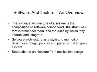
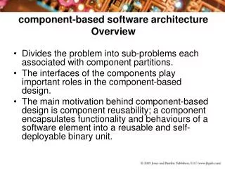
What is An Architecture?It is an Enabler • Definition of Software Architecture: A software architecture is characterized by a particular combination of software components and connections. The SCA provides a framework, not functionality. • The JTRS Software Communications Architecture(SCA) Enables: • porting of “waveforms” • reuse of software (largely internal to development organization) • extensibility of hardware and software (emphasis on modeling) • interoperabilitybetween platforms • use ofcommercial product lines (as it gains commercial acceptance)
RF GPP GPP DSP DSP What is the SCA? • Independent ofwaveform functionality • “Component oriented” – profiles describe HW / SW components • Defines SW Interfaces for data connection and management control • Defines a common management framework • to configure, connect and tear-down distributed applications • The JTRS SCA specifies an open, non-proprietary architectural framework Domain Mgr POSIX CORBA FPGA GPP Devices
To Applications RF Analog ADC RF RF Recompilation Domain Mgr Domain Mgr POSIX CORBA POSIX CORBA GPP GPP GPP GPP FPGA DSP DSP GPP DSP FPGA Devices Devices How can the SCA Benefit DoD? “same” waveform software runs on different hardware sets Recompilation
Criteria for the SCA • Based on Open, Commercial Standards • OMG, IEEE, IETF • Supports a Family of Radios • Interoperable, • Programmable • Scaleable (handheld to fixed-station), • Maximizes Platform Independence of Software from Hardware • Application and Device Portability & Reuse • Rapid Technology Insertion Over Time • Extendible to New Waveforms and/or Hardware Components
Applications Core Framework (CF) Operating Environment (OE) Non-CORBA Commercial Off-the-Shelf (COTS) Security Components Non-CORBA Non-CORBA Modem I/O Components Components Physical API RF Link, Network Security Modem I/O Modem Security Link, Network I/O Security Adapter Components Components Components Components Components Adapter Adapter Adapter MAC API LLC/Network API Security API LLC/Network API I/O API (“Logical Software Bus” via CORBA) Core Framework IDL CF CF CORBA ORB & CORBA ORB & Services & Services & Services Services Applications (Middleware) Applications (Middleware) Operating System Network Stacks & Serial Interface Services Network Stacks & Serial Interface Services Operating System Board Support Package (Bus Layer) Board Support Package (Bus Layer) Red Hardware Bus Black Hardware Bus SCA Software Structure
The SCA “Model” • Software • Operating Environment • POSIX-based operating system (OS) • CORBA / Interface Definition Language (IDL) • JTRS Core Framework (CF) • Domain Profile (XML-based) • Hardware • Classes (Operations and Interfaces) • Rules for Implementation • How the Architecture is applied to products • The SCA does not … • specify implementation-level details • define all the elements or interfaces for a SDR • guarantee portability
SCA Core Framework Definition • The SCA CF is a “core” set of interfaces that provide an abstraction of the underlying software and hardware layers for software application designers • CF Interfaces (defined in IDL) consist of: • Base Application Interfaces (Port, LifeCycle, TestableObject, PortSupplier, PropertySet, ResourceFactory, and Resource) that can be used by all software applications • Framework Control Interfaces (Application, ApplicationFactory, DomainManager, Device,LoadableDevice, ExecutableDevice, AggregateDevice, andDeviceManager) that provide control of the system • Framework Service Interfaces (File, FileSystem, and FileManager) that provide interfaces for distributed file access services to software application components • Domain Profile that describes the properties of hardware devices and software components in the system and enables application deployment
Power activates: OS ORB Device Managers 1 Domain Manager 1 Domain Mgr1 Device Mgr per CORBA-capable processor All Dev Mgrs report toDom Mgr Each Device Manager responsible for booting its Devices and Services DCD DCD tells Dev Mgr what HW devices exist HardwareDevices HardwareDevices HardwareDevices • 1 Domain Mgr per JTR Set • 1 Device Mgr per CORBA Capable processor • Device Mgr starts up its device (in parallel) • Primarily works at “power on” CORBA-capable processor CORBA Domain Manager Device Manager Platform Mangement
Domain Mgr Knows Devices,Applications, & Resources HMI access uses Dom Mgr HMI DCD defines characteristics of devices to be loaded SAD describes the components that comprise an application DomainManager One Dev Mgr per CORBA-capable processor An App Fac is created for each installapplication, i. e. SAD SAD DeviceManager ApplicationFactory DCD Resources Devices Application On starting Application HardwareDevices • XML Profiles provide application Metadata • “resource” + Software Profile Descriptor = a “component” • “install” creates an Application Factory • An Application Factory starts up an Application instance
ControlData CollectionofFunctionalityProgrammer-Defined Get Port StartStop User-DefinedInterfaces InitializeRelease Run Test Resource • A resource “packages” together object code that runs within a processor • Provides set of “control” operations (primarily used by Core Framework) • Functionality and Interfaces (ports) are supplied by programmer
ControlData CollectionofFunctionalityProgrammer-Defined Get Port StartStop Hardware Aggregate User-DefinedInterfaces InitializeRelease Run Test Device State LoadExecute • A Device IS a resource that provides a HW abstraction • State reflects state of the hardware: Usage, Admin, Operational
Core Framework IDL Relationships Base Application Interfaces Framework Control Interfaces Framework Services Interfaces
SCA Base Application Interfaces • Port • used to connect Resource Components • LifeCycle • used to initialize or release Resources • TestableObject • used to test a Resource • Port Supplier • used to obtain a specific port • PropertySet • provides operations to access Resource properties • ResourceFactory • Used to create / tear down Resources • Resource • provides common interface for Resource control and configuration
SCA Framework Control Interfaces • Application • CF provided container for Resources that make up application • provides interfaces for control, configuration, status and tear-down • ApplicationFactory • used to create application (waveform) instances • based on Domain Profile • allocates SW (Resources) to HW (Devices) - allocates capacities • connects Resources that make up application • performs initial configuration • DomainManager • Provides interface for DeviceManager, Device and Application registration • Provides access to registered DeviceManagers, installed and Running applications, the platform’s FileManager • Provides interface to HCI to access the domain and its capabilities (Devices and Applications)
SCA Framework Control Interfaces (cont.) • Device • A software proxy for a physical hardware device • Represents CF interface between applications and devices • Typically one Device per HW device • Loadable, Executable, and Aggregate Devices extend behavior of the Device Class • DeviceManager • Manages a set of logical Devices and services
SCA Framework Services Interfaces • File • Provides access to files within the radio • Allows access across processor boundaries (distributed file systems) • FileSystem • Enable remote access to physical file systems • Allows creation, deletion, copying, etc of files • FileManager • Manages multiple distributed FileSystems • Looks like a FileSystem to client
SCA Domain Profile • A set of files that describe HW and SW components making up an SCA system domain • eXtensible Markup Language (XML) format • Document Type Definitions (DTDs) describe the files [Customized to better address Software Radio Needs]
SCA Status • SCA is being accepted by Industry • An “SCA equivalent” exists within the family of OMG Standards • Commercial tool vendors and industry have provided some SCA tools • PrismTech, Zeligsoft and CRC • The SCA has undergone three phases of architectural validation and provides the backbone for JTRS Cluster 1 • The SCA and its underlying technologies target a GPP based platform however many of the abstractions are applicable to other processing environments • The JTRS program office has a plan in place to continue to evolve the SCA
Schedule for standardization of SCA related specifications at the Object Management Group (OMG) Deployment & Configuration Lightweight Services Lightweight Log Services PIM and PSM for SW Radio Lightweight CCM Specification Adoption Nov 03 June 04 Feb 04 July 03 Nov 03 Finalization Nov 04 Jul 04 April 05 Formal Standard Formal spec Adoptedspec Finalized spec Sep 05 Software Communications Architecture Note: All dates represent estimated OMG schedules
SWRadio MDA Principles • UML Profile for SWRadio extends UML for SWRadio tool support: validation, system engineering, and SWRadio component development • PIM has been primarily structured as a set of facilities each addressing a key aspect of SWRadio • Well-defined set of modeling conventions • Naming conventions • Modeling conventions • Subset of UML notation • Specific semantics of this notation in the context of this PIM • Conforms to MDA • PIM can be transformed to different component platforms • CORBA-PSM, Java-PSM, etc. • Compatible with existing OMG standards • MOF • UML
Meta Object Meta-Meta-Model Layer (M3) Facility (MOF) Domain & Platform Technology profiles «instanceOf» UML Profiles for SWRadio, CORBA, Java, C++, XML Schema «extends» OMG UML Meta-Model Layer (M2) «instanceOf» «instanceOf» Profiles M1 Data Waveform, Device, Radio Infrastructure & Service Components PIMs Waveform, Device, Radio Infrastructure & Service Components PSMs, CF Interfaces, XML Descriptors «refine» PIM & PSM Layer (M1) «instanceOf» Waveform, Device, Radio Infrastructure & Service PSM Components & Artifacts (XML Descriptors, Executables) Runtime or Deployed Artifacts Layer (M0) SWRadio MDA Principles, cont’d
SWRadio Development Viewpoints • To address the issues of the different actors involved in SWRadio product developments, the current profile was developed with three main viewpoints in mind: • the viewpoint of application and device developers, • the viewpoint of infrastructure/middleware providers, and • the viewpoint of SWRadio platforms providers. • These three viewpoints define distinct sets of concepts (and stereotypes) that are required in different contexts.
UML Profile for SWRadio • To be consistent with the three development viewpoints, the UML Profile for SWRadio is partitioned in three main packages: • the Applications and Devices Components, • the Infrastructure, and • the Communication Equipment package. • Each package defines the set of concepts and UML stereotypes required to perform a specific role in the development of an SWRadio product.
UML Profile for SWRadio Application & Device Components • Application Components • Contains the component stereotypes for application developers • Application, ApplicationResourceComponent, LayerResource (Data Link, MAC, Physical) • Base Types • Contains the common types for defining SWRadio components. • Interface & Port Types • Contains the port and interface stereotypes for SWRadio interfaces and components • Device Components • Contains the component stereotypes for device developers • Logical Device, Loadable and Executable • Properties • Contains property stereotypes for SWRadio components • Configure, Query, Characteristic, Capacity • Resource Components • Contains the interface and component stereotypes for waveform and device developers • ControllableComponent, LifeCycle, PropertySet, ResourceComponent, etc.
UML Profile for SWRadio Infrastructure • Radio Services • Common services within the radio platform that are utilized by applications • Managed component service • Radio Management • RadioSet, RadioSystem, and Device Management • Communication Channel • Physical, IO, Security, and Processing Channel • Captures the relationships between channels and SWRadio devices • Application Deployment • Components and Artifacts stereotypes for the deployment of: • Waveforms on communication channel’s distributed devices • Radio Services within the Radio Set
UML Profile for SWRadio Communication Equipment • Stereotypes for SWRadio devices • Communication Equipment describes the relationships and attributes that are appropriate for radio devices. • Crypto Device - performs encryption and decryption on asset of data. • I/O Device - describes the relationships and attributes that are appropriate for I/O devices • Antenna, Amplifier, Filter, Frequency Converter, audio, serial, etc. • Power Supply - provides electrical power to other devices. • Processor Device - processes digital or analog data. • Port Types • Analog & Digital • Property Types • Characteristic & Configure
SWRadio PIM Facilities • Common Radio Facilities • Provides common service definitions that are applicable for all applications (waveforms or radio control) • File Services, OMG Lightweight Services (log, event, naming, etc.) • Common Layer Facilities • Provides interfaces that cross cut through facilities that correlate to layers. These interfaces can be viewed as building blocks for SWRadio components that realize multiple interfaces. • Protocol Data Unit, Error Control, Flow Control, Measurement, Quality of Service, and Stream Facilities
SWRadio PIM Facilities, cont’d • Data Link Facilities • Link Layer Control (LLC) facilities. LLC layer provides facilities to upper layers, for management of communication links between two or more radio sets. • Data Link Layer (Connectionless, ConnectionLess Ack, Connection), and Medium Access Control Facilities • I/O Facilities • Defines the configuration properties for Audio and Serial Facilities
SWRadio PIM Facilities, cont’d • Physical Layer Facilities • Modem Facilities • The modem facilities include all digital signal processing elements required to convert bits into symbols and vice versa. • RF/IF Facilities • The RF/IF Facilities is used to configure and control the basic devices of the physical channel. The granularity at which these interfaces are implemented is not specified. • Radio Control Facilities • Provides for interfaces for radio and channel management.
SWRadio PSM • Automatic PSM generation from PIM and profile definitions • Transformation rule set specified in the specification • Platform Specific Model • CORBA Modules • CF • StandardEvent, PortTypes • DfSWRadio • CommonLayer, DataLinkLayer, CommonRadio, PhysicalLayer, RadioControl • DSFileServices • XML Schema • Properties • Communication Channel • Physical Layer Properties • POSIX • Other PSMs could be defined
SWRadio Lessons Learned • Benefits • Promotes separation of design / development concerns • Nothing new (good SW Engineering principles) • MDA approach requires more formal/complete models • Enables artifact generation • Impediments to adoption • Lack of tools (transformation, generation, UML extension, MOF infrastructure) • Programmatic conflicts exist regarding integrating new specs into an existing product family
Summary • The SCA provides a platform and development language independent architectural framework upon which SDR (and other distributed, component based) applications can be built. • The underlying platform independent SCA model has been emphasized in areas such as the OMG family of specifications • The SCA “works” however there are areas for evolution • Resource Constrained processing environments • Extendiblity into other platform specific middlewares and OEs