Download
1 / 32
350 likes | 924 Views
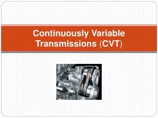
2004 International Continuously Variable and Hybrid Transmission Congress September 23-25, 2004 Control and Operating Behavior of Continuously Variable Chain Transmissions Roland Mölle Introduction – Chain-CVT Clamping Systems Ratio Control Design during Range Shifts in Autarkic Hybrid

E N D
2004 International Continuously Variable and Hybrid Transmission Congress September 23-25, 2004 Control and Operating Behavior ofContinuously Variable Chain Transmissions Roland Mölle
Introduction – Chain-CVT • Clamping Systems • Ratio Control Design during Range Shifts in Autarkic Hybrid • Expanded Control Layout for Universal Use in Chain Variator Applications • Summary Presentation Outline
PIV Chain Converter Chain Secondary Pulley Primary Pulley Hydro-Mechanical Torque Sensor Introduction
Typical CVT chain of amodern passenger car:Audi multitronicTorque Capacity up to 300 NmNominal Power 162 kW (V6-3.0) Pull type Chain in Audi/LuK CVT
Introduction – Chain-CVT • Clamping Systems • Control Design for Range Shifts in Autarkic Hybrid • Expanded Control Layout for Universal Use in Chain Variator Applications • Summary Presentation Outline
Main Advantage: Pressure • Oil flow on demand Transducer Pulley 1 Disadvantages: • Torque information supplied by engine controller: Poor dynamics and limited accuracy • Need for high over clamping for security reasons or additional measures • Oil flow always at maximum pressure level Pulley 2 Directional Control Valve Constant Pressure Oil Supply Constant Pressure System
Advantages: Torque • Clamping pressures are automatically achieved without superior control • High dynamically set clamping pressures due to the “pump function” • Clamping pressure and speed ratio control independent Sensor Pulley 1 Four Edges Spool Valve Line Pressure Valve Pulley 2 Actuator Speed Ratio Control Main Disadvantage: Constant Flow Oil supply • Permanent, constant oil flow required Pressure Differential HydraulicControl Unit Valve Constant Oil Flow System (PIV)
Movable sensor plate sF (axial movement of sensorplate) Characteristics: • Torque sensor pressure – proportional to torque at the shaft • Additional “pump function” at high torque gradients Conventional Torque Sensor(System PIV)
400 40 p p Pcyl1 Pcyl2 CYL1 CYL2 p p pTorque Pump TORQUE PUMP bar Nm e r u s s 200 Torque 20 shift speed ds/dt e r P 100 10 0 0 mm -1,5 -1 -0,5 0 0,5 1,5 Slide valve travel Characteristic Curve of Actuator in Conventional PIV Clamping Systems
Introduction – Chain-CVT • Clamping Systems • Control Design for Range Shifts in Autarkic Hybrid • Expanded Control Layout for Universal Use in Chain Variator Applications • Summary Presentation Outline
The Autarkic Hybrid • Opel Astra Caravan • 60 kW Diesel engine • 10 kW electric motor (120V) • i2-CVT gearbox Range shift in Autarkic Hybrid raised the need for improved speed ratio control: Extremely high torque gradients during range shift(CVT engaged vs. disengaged) Error signal <0,002 required Driveline of the Autarkic Hybrid
Selection of control parameters: Absolute value of deviation u 0 Algebraic sign of deviation u Variation of param. (gain scheduling): Value of control variable u CVT Controller, Variable in Structure
Ratio ofclamping forces FAn z = FAb • Main disturbancevariables: • Torque • Speed Ratio ... lead to a change in required z-ratio for steady state operation pAb FAb=pAb.Az Az FAn=pAn.Az Az pAn Influence of Disturbance Variables
Problem: Improved control system is needed for speed ratio control at SYN (i=0,458) during range shift. Solution: Disturbance feedforward (torque) Extension of the Speed Ratio Controller
The taken measures resulted in a significant improvement of the quality of speed ratio control and reliability of range shifts. Apply same principles to the CVT controller for universal use: • Regard to further disturbance variables • Improved control over the whole spreading range (improvements in quality, efficiency etc.) • Enable different control strategies: ratio based strategies (e.g. ground speed pto) vs. di/dt control (passenger car / transportation work) Results and further Aims
Introduction – Chain-CVT • Clamping Systems • Control Design for Range Shifts in Autarkic Hybrid • Expanded Control Layout for Universal Use in Chain Variator Applications • Summary Presentation Outline
Algebraic compensation Characteristic z-map • Further disturbance variables: • Speed (rotating hydraulic cylinder) • Spring (basic clamping force) • Main disturbance variables torque and speed ratio lead to: Pulley Misalignment, shaft deflection, pulley distortion, … … change in clamping force ratio Disturbance Variables
DisturbanceVariables Distrubancefeedforward z-map Mathematic Compensation E=mc2 setpoint LinearController CVT actualvalue Extension of the Control Structure
Prerequisites for adaptation: Adaptation DisturbanceVariables • Steady state(T, n, manipulated var.) • … Distrubancefeedforward z-map Mathematic Compensation background task (duration ?) E=mc2 constant task time (e.g. 5ms) Question: Where to get the z-map from ? Output of Linear Controller supposed to be Zero in steady state! setpoint LinearController CVT actualvalue Adaptation of z-map
Adaptation of the sampling points: Value of the manipulated variable from linear controllerx weighting factor. • Weighting functions: • Gauss • Cone • ... Adaptation Law
START Visualization and Discussion of the Adaptation Process
Power demand leads to desired engine speed. • New engine speed is achieved by changing the CVT’s speed ratio i. • Change in speed ratio di/dt affects the available torque at the wheel T2! • Controlling the rate of speed ratio change is favorable CVT in Drive Train Configuration
Adaptation DisturbanceVariables Distrubancefeedforward z-map Mathematic Compensation E=mc2 setpoint di/dt pdyn LinearController f(di/dt,n,geometry) Modification of the control structure: • Delete Feedback Loop • Stop Adaptation Process • Replace Controller setpoint speed ratio speed ratio di/dt CVT Control of the Rate ofSpeed Ratio Change di/dt
pdyn = ds/dt / ( ACYL·D ) • Axial pulley speedds/dt = f ( di/dt, geometry ) • Damping coefficientD = f ( speed… ) * ü = 1/i Control of the Rate ofSpeed Ratio Change di/dt
Introduction – Chain-CVT • Clamping Systems • Control Design for Range Shifts in Autarkic Hybrid • Expanded Control Layout for Universal Use in Chain Variator Applications • Summary Presentation Outline
Quality of speed ratio control was significantly improved • The control structure was implemented using a RCP- system running under Matlab/Simulink (xPCTarget) and is currently running on a test rig • For use in tractor applications it was also implemented on a typical electronic control unit (C167) both manually and using code generation (dSpaceTargetLink 2.0) • Gathered z-maps can be used for different purposes (scientific work, onboard diagnostic purposes etc.) • Further optimization possible (improved di/dt, z-max) Summary
2004 International Continuously Variable and Hybrid Transmission Congress September 23-25, 2004 Control and Operating Behavior ofContinuously Variable Chain Transmissions Roland Mölle

![The Impact of [independent variable] On [dependent variable] Controlling for [control variable]](https://cdn0.slideserve.com/430545/the-impact-of-independent-variable-on-dependent-variable-controlling-for-control-variable-dt.jpg)