Download
1 / 27
290 likes | 505 Views
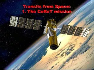
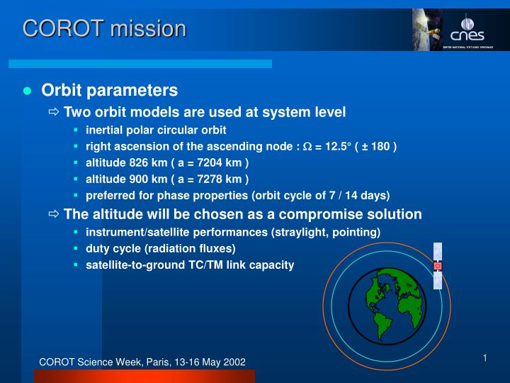
COROT mission. Orbit parameters Two orbit models are used at system level inertial polar circular orbit right ascension of the ascending node : = 12.5° ( ± 180 ) altitude 826 km ( a = 7204 km ) altitude 900 km ( a = 7278 km ) preferred for phase properties (orbit cycle of 7 / 14 days)

E N D
COROT mission • Orbit parameters • Two orbit models are used at system level • inertial polar circular orbit • right ascension of the ascending node : = 12.5° ( ± 180 ) • altitude 826 km ( a = 7204 km ) • altitude 900 km ( a = 7278 km ) • preferred for phase properties (orbit cycle of 7 / 14 days) • The altitude will be chosen as a compromise solution • instrument/satellite performances (straylight, pointing) • duty cycle (radiation fluxes) • satellite-to-ground TC/TM link capacity
COROT mission • Orbit parameters • The orbit will not be kept phased after commissioning • risk of sun glare in case of semi-major axis correction maneuver • semi-major axis drift over 5 years : - 7 km (atmospheric drag) • orbit period stability over 6 months : better than 1 s Xs+ Sun direction Thruster along Xs Eclipse
COROT mission • Orientation of the satellite - flight domain Sun
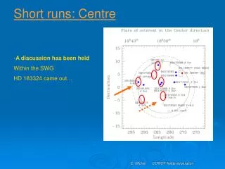
COROT mission • The sky observed by COROT
Xs+ Zs+ Ys+ COROT mission • Satellite design / axes Equipment bay Upper compartment with sensitive equipment Fine thermal regulation subsystem
COROT mission • Platform design • “PROTEUS Evolution” family • series of 5 platforms • upgraded electrical and AOCS chains • Li-Ion battery • higher capacity (80 A h) no more problem of power supply in Safe Hold Mode • lower thermal dissipationthe battery sidewallcan withstand any solar incidenceno need to rotate on the boresight axis after 5 months • New Magneto Torquer Bars • higher capacity (180 A m2)better convergence of the Safe Hold Mode • equipment driven by a proportional control lawno more pointing disturbances due to MTB activations • Other features : new star trackers (SODERN), 2-antenna GPS
COROT mission • New mission schedule • Thermal constraints shrunk to payload constraints • the Ys+ satellite wall (focal unit radiator) must be in the shadeas much as possible • No more 180° rotation on Xs between CP and EP • No more EP2 critical thermal configuration for payload design • Several possibilities for the scheduling • Exploratory Programs can be carried out either at the beginningor at the end of a 6-month period • an alternate schedule CP1, EP1, CP2, EP2 is operationally recommended • Focal unit radiator temperature worst cases in 1b and 2b • 1b and 2b zones crossed by the Line of Equinoxes • temperature depending on direction of observation and roll angle
Zs- Zs- Ys+ Ys+ Xs+ Xs+ Xs+ Xs+ Ys+ Zs- Zs- COROT mission 180° rotation on Zs • Previous schedule“Peace and Love” Spring Line of Equinoxes Line of nodes Satellite axes in a fixed orbital reference frame ROF Summer Earth orbit Solar declination up to +23° Central Program 1 Central Program 2 Center (18h50) Anticenter (6h50) S ZOF YJ2000 XJ2000 XOF Winter Exploratory Programs 1 & 2 Solar declination down to –23° Ys+ Equatorial plane 180° rotation on Xs 180° rotation on Xs 12.5° Autumn 180° rotation on Zs
Zs- Zs- Ys+ Xs+ Ys+ Xs+ COROT mission 180° rotation on Zs • Updated schedule“Apple pie” Spring Line of Equinoxes Line of nodes Satellite axes in a fixed orbital reference frame ROF 1a 2b Summer Earth orbit Solar declination up to +23° Central Program 1 Central Program 2 Center (18h50) Anticenter (6h50) S ZOF YJ2000 XJ2000 XOF Winter Exploratory Programs 1 & 2 Solar declination down to –23° 1b 2a Equatorial plane 12.5° Autumn 180° rotation on Zs
COROT mission • Performance management • Performance management consists in choosing the most favorable edge for each observing run • a slight drop in periodic performances (compatible with the requirements) can be tolerated for the EP observing runs • white noise bphot = f(1/ Tobs) in Fourier space spectrum analysis less sensitive to periodicperturbations (hidden lines) in EP runsi 2 Ai / ( bphot (T)) 1 / Qi < 100 Hz • To define a scenario, the users shall have a series of criteria • direction of observation • roll angle to optimize the projection of the targets onto the CCD • criticity of the thermal regulation (level, variability) function of the roll angle • criticity of the straylight intensity if any
Ys+ 0E1 CCD A1 CCD E1 Right Left Right Left Zs+ 0A1 0E2 CCD A2 XV CCD E2 Right Left Right Left 0A2 Buffer dump direction Frame transfer direction YV COROT mission • Focal unit configuration 2.70° 3.05°
S E Ys+ Zs+ COROT mission angle for optimum power budget : = arctan (-tan sin) = 5.25° • Spacecraft roll domain winter CP and EP n°2 Objective : ± 20°
E S Zs+ Ys+ COROT mission angle for optimum power budget : = arctan (-tan sin) = 5.25° • Spacecraft roll domain summer CP and EP n°1 Objective : ± 20°
COROT mission • Spacecraft roll domain • The ± 20° requirement may prove to be difficult to meet • The following points must be checked • power budget (solar flux incidence) CNESLi-Ion battery likely to improve the power budget • masking of the star trackers’ field of view by the Earth ASPIAccommodation of the SED-16 star trackers to be worked on • payload thermal constraints CNES, Soditech+20° or -20° reachable for a given observing run TBC • Set of conclusions available in September
System progress report • Technical status • Major instrument sub-system PDR held in the coming months • mechanical, thermal and optical architecture in progress • much work on straylight rejection and thermal regulation performances • System engineering activity currently focused on • command an control interfaces • on-board software • light curve corrections and data processing • ground segment architecture • Ground Segment & System Review in November 2002 • Contract with the launcherto be signed this year
AOCS performances • Pointing and AOCS • Stringent pointing stability requirements • coupled attitude/photometry noise if the image spot moves • random : 0.5 arcsec (1 sigma) • periodic : 0.2 arcsec (amplitude) for 2-ppm spectral lines in [0.1 ; 1] mHz • Instrument used for angle error measurements • random and periodic sensor errors divided by 10 • thermo-elastic variations between star tracker and payload frames removed • Small gaps of perturbations (< 3 % of the time) should remain during : eclipse entries/exits, MTB activations and solar panels rotations 1999 preliminary budget
AOCS performances • Pointing and AOCS AOCS loop modified ecartometric data generated by each seismology channel (frequency 1 Hz) 2 stars used by the ecartometric algorithm (least square method) breathing corrected by real time focal length estimate Target quaternion PROTEUS Sensors Estimator Kalman Filter Controller Actuators Wheels MTB Gyroscopes Star Tracker COROT payload Chain 1 (, , )1 or 2 A1 E1 Chain 2 A2 E2
Ys Xs Zs AOCS performances • Requirements at spacecraft levelThe PSF movement on the CCD surface is split up into 3 spacecraft rotations • Random requirements (1 ) (inertia Iyy, Izz >> Ixx) • 0.3 arcsec on Ys, Zs • 24 arcsec on Xs • Periodic requirements (0-peak amplitude) • 0.1 arcsec on Ys, Zs • 4.4 arcsec on Xs • Requirements at instrument levelBased on temporary worst case estimates • Random requirements (1 ) lever effect : 1,000 pixels • 0.09 arcsec on Ys, Zs pixel size : 2.32 arcsec • 15 arcsec on Xs • Thermo-elastic periodic requirements (0-peak amplitude) • 0.06 arcsec on Ys, Zs • 9 arcsec on Xs
AOCS performances • Spacecraft dynamic simulations (1) • work undertaken by CNES and ASPI • CNES as prime • ASPI as industrial architect • objectives • characterization of each perturbation (environment, hardware) • consolidation of the requirement set • reference data for further system analyses • 6-month activity run in 3 steps • preliminary analysis • simulation software upgrade • simulation campaign • results available since December 2002
AOCS performances • Spacecraft dynamic simulations (2) • preliminary analysis • kinematic filter replaced by a dynamic Kalman filter(state vector including position, speed, drift, perturbation torque)gyrometer noise divided by 3, robust for inertial pointing • choice of the reaction wheel set configuration • choice of a 0.05 Hz bandwidth after noise/stability trade-offcontroller noise outside the scientific bandwidth • worst case identification for subsequent simulationssolar wings at 90° and Sun in the orbit plane • PASIFAE simulation software upgrade • dynamic filter implementation • MTB proportional control law • Simulations • assessment of each external/internal perturbation torque • global simulations for system analysis
AOCS performances Kinematic filter Dynamic filter
AOCS performances Scientific bandwidth 0.005 Hz 0.05 Hz
AOCS performances • Random noise budgetSimulation-based • The requirements are met in any case • Typical 2D value of 0.3 arcsec
AOCS performances Scientific bandwidth • Periodic noise budget • The instrument harmonic errors are not rejected • 9 arcsec on Xs at 0 • 0.06 arcsec on Ys, Zs at 0 • Many perturbation lines on Ys and Zs due to external environment • gravity gradient at 20 • Earth magnetic fieldeven harmonics at 20, 40, 60 • Most of 2D pointing noise requirements are met • Frequency band polluted< 100 Hz
AOCS performances • Conclusion • The simulations give hope for a random noise of 0.3 arcsec (1) • The duty cycle is improved (+ 2.7 %) by the removal of the MTB periodic perturbations • Despite several lines due to gravity gradient and magnetic torque in [0.1 ; 1] mHz, the spectrum pollution is less than 100 Hz • The periodic requirements should be met after sensibility study and consolidation of the payload thermo-optical performances • angle error measurement simulations in progress • improvement expected from real time focal length estimateif 6 mv 8 and 500 pixels between stars at least
AOCS performances • Other works in progress • Optical distortion variability under assessment CNES/LAM • for seismology channel : to consolidate the angle error budget • for exoplanet channel : to check the amplitude of the border/chromatic noise (in the field of view) • set of optical performances under verification point by point • Mission mode architecture study CNES/ASPI • inventory of AOCS loop modifications • Command & Control • Transition from the PROTEUS standard mode • DHU performances and channel switching feasability • FDIR • Multi-mode AOCS simulator implementation CNES • Safe Hold Mode simulations (Monte Carlo) • validation of the Mission mode performances