Download
1 / 16
170 likes | 190 Views
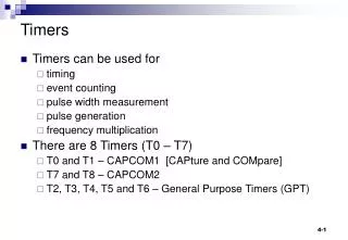
Timers. Timers can be used for timing event counting pulse width measurement pulse generation frequency multiplication There are 8 Timers (T0 – T7) T0 and T1 – CAPCOM1 [CAPture and COMpare] T7 and T8 – CAPCOM2 T2, T3, T4, T5 and T6 – General Purpose Timers (GPT).

E N D
Timers • Timers can be used for • timing • event counting • pulse width measurement • pulse generation • frequency multiplication • There are 8 Timers (T0 – T7) • T0 and T1 – CAPCOM1 [CAPture and COMpare] • T7 and T8 – CAPCOM2 • T2, T3, T4, T5 and T6 – General Purpose Timers (GPT)
General Purpose Timers (GPTs) • The five GPT’s are 16-bit timers that are grouped into the two timer blocks GPT1 and GPT2. • Block GPT1 contains 3 timers/counters with a maximum resolution of 16 TCL(TCL = 50ns for fCPU = 20MHz) • Block GPT2 contains 2 timers/counters with a maximum resolution of 8 TCL and a 16-bit Capture/Reload register (CAPREL).
GPT1 Block From a programmer’s point of view, the GPT1 block is composed of a set of SFR’s as summarized below. Those portions of port and direction registers which are used for alternate functions by the GPT1 block are shaded.
Timers T2, T3 and T4 • Four basic modes • Timer • Gated timer • Counter • Incremental interface mode – for incremental encoders • All timers can count up or down • When a timer register overflows from FFFFH to 0000H (when counting up), or when it underflows from 0000H to FFFFH (when counting down), its interrupt request flag (T2IR, T3IR orT4IR) in register TxIC will be set. • Each timer has an alternate input function pin (TxIN) associated with it which serves as the count input in counter mode, or as the gate control in gated timer mode. x – refers to the timer number
Timer 2, 3 and 4 Physical microcontroller pin TxUD – External Timer Up/Down control TxIN – External clock input T3OUT – External output pin from Timer3 fcpu – CPU clock input to prescaler (which divides by 8 ,16, 32, …1024)
T2, T3 and T4 Timers (contd.) • T3 is the called core timer • The count direction (Up/Down) may be programmed via software or may be dynamically altered by a signal at an external control input pin. • Each overflow/underflow of core timer T3 is latched in the toggle Flip-Flop T3OTL and may be indicated on an alternate output function pin. T2 and T4 do not have this feature. • Some timer modes require the use of more than one timer. For example : The auxiliary timers T2 and T4 may additionally be concatenated with the core timer, or used as capture or reload registers for the core timer.
Timer Control Register T3CON – Timer 3 Control Register (bit addressable)
T3 in Timer mode The 3 TxI bits in TxCON determine the precaler factor as shown in the table below. n = 3..10 Note the x in TxUD, TxUDE, TxI etc. refers to the timer number
T3 in Timer mode UP(0)/DOWN(1)
Timer 3 generating a fixed delay // Initialise timer 3 for Timer mode, prescaler 101 (÷256), timer stopped // count down, disable external up/down, T3OTL output disabled T3CON = 0x0085; //00000 000 10 000 101 // timer period = prescaler / fcpu = 256/20MHz = 12.8uS // delay required = 400000uS. Timer value = 400000/12.8 = 31250 // Clear T3 interrupt request bit, load timer value and run timer T3IR = 0; T3 = 31249; // 1 less than number of counts required T3R = 1; /* T3 is now decremented by hardware every 12.8uS, after 31250 decrements the interrupt request flag is set. The program should poll/test this flag. */ while (T3IR == 0); // wait until interrupt request is set
Example - Timer delay #include <stdio.h> /* standard I/O .h-file */ #include <reg167.h> /* special function registers for 167’s */ /*************************************************/ /* Use Timer 3 to generate a delay of 0.4 seconds*/ /*************************************************/ void main (void) { /* initialize the serial interface */ #ifndef MCB167 /* do not initialize with Monitor-166 */ P3 |= 0x0400; /* SET PORT 3.10 OUTPUT LATCH (TXD) */ DP3 |= 0x0400; /* SET PORT 3.10 DIRECTION CONTROL(TXD O/P)*/ DP3 &= 0xF7FF; /* RESET PORT 3.11 DIRECTION CONTROL(RXD i/p)*/ S0TIC = 0x80; /* SET TRANSMIT INTERRUPT FLAG */ S0RIC = 0x00; /* DELETE RECEIVE INTERRUPT FLAG */ S0BG = 0x40; /* SET BAUDRATE TO 9600 BAUD */ S0CON = 0x8011; /* SET SERIAL MODE */ #endif . . . see next slide, which goes here. . . }
//Initialise timer 3 for timer mode, prescaler=256, timer stopped //count down, disable external up/down T3CON = 0x0085; //0000000010 000 101 while (1) //do this endlessly! { printf("\nPress a key to start timer\n"); _getkey(); // special Keil function to wait for a key // Clear T3 interrupt request bit, load timer value and run timer T3IR = 0; T3 = 31249; T3R = 1; printf("Timing started\n"); // Now wait for T3 interrupt request bit to be set to 1 // This should take 31250 x 12.8uS = 400000uS = 400ms = 0.4S // based on a 20MHz cpu clock frequency while( T3IR == 0); T3R = 0; //Stop timer //When loop terminates we know the required delay has elapsed printf("400 milliseconds has elapsed\n"); }
Gated Timer Mode This mode is used for measuring the period of pulses n = 3..10 Timer mode bits TxM gate open TxIN – provides the gating of the clock
The 3 bits TxI determine the transition for counter increment/decrement Counter mode
Concatenation of Timers Concatenation of Core Timer T3 and an Auxiliary Timer