Download
1 / 47
500 likes | 549 Views
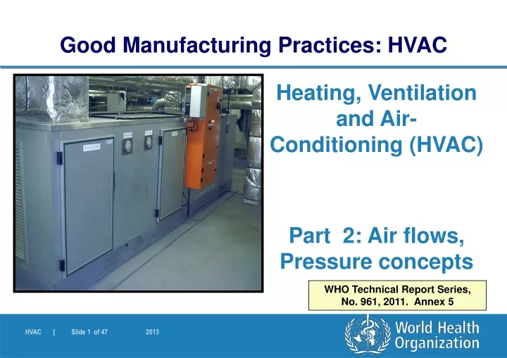
Good Manufacturing Practices: HVAC. Heating, Ventilation and Air- Conditioning (HVAC) Part 2: Air flows, Pressure concepts. WHO Technical Report Series, No. 961, 2011. Annex 5. HVAC. Objectives To continue from previous section of Part 1, now focus on:

E N D
Good Manufacturing Practices: HVAC Heating, Ventilation and Air- Conditioning (HVAC) Part 2: Air flows, Pressure concepts WHO Technical Report Series, No. 961, 2011. Annex 5
HVAC Objectives To continue from previous section of Part 1, now focus on: • Air filtration and air flow patterns • The role of HVAC in dust control • HVAC system design and its components (part 3) • Commissioning, qualification and maintenance (part 4)
HVAC Air Filtration • Degree of filtration of air is important to prevent contamination • Type of filters to be used is dependent on: • Quality of ambient air, • Return air / re-circulation • Air change rates • National requirements • Products and required class of clean room etc. • Manufacturer to determine, select and install appropriate filters for use 4.2.1, 4.3.3
HVAC Levels of protection and recommended filtration 4.2.1 - 2
HVAC Contamination can be prevented by considering: • Appropriate materials of construction of HVAC components • Placement of components (e.g. upstream of final filters) • Design and appropriate access (from outside) to dampers, filters and other components • Personnel operations and protection • Airflow direction • Air distribution component design, installation and location • Diffusers (type, design, location) • Air supply and air exhaust location 4.2.4 – 4.2.10
HVAC Induction diffuser
HVAC Perforated plate
HVAC Swirl type diffuser
HVAC Airflow patterns • Filtered air entering a production room or covering a process can be • turbulent, or • unidirectional (laminar) • GMP aspect • economical aspect • Other technologies: barrier technology/isolatortechnology.
Unidirectional/laminar displacement of dirty air Turbulent dilution of dirty air HVAC Airflow patterns
Airflow patterns Prefilter AHU Main filter 2 3 1 Unidirectional Turbulent Turbulent HVAC
HVAC Unidirectional airflow (UDAF) Often used in weighing and sampling areas (Airflow Protection Booths) and provides: • Dust containment and product and operator protection Note: For Airflow Protection Booths (APB): • Airflow velocity should not affect balance (may be lower than for Class A areas) • Position of material, balance, operator determined and validated – no obstruction of airflow or risk 4.3
HVAC Airflow patterns Workbench (vertical) Cabin/booth Ceiling
HVAC Unidirectional airflow (UDAF): • Sampling and weighing area classification – same as other processing areas following sampling and dispensing • Dust containment shown through smoke tests as part of validation / qualification • Location and type of return and exhaust grilles • Cleaning and maintenance • Will discuss examples in the following figures 4.3.
HVAC Infiltration • Prevent infiltration of unfiltered, contaminated air from outside • Facilities normally under positive pressure to the outside • Building structure well sealed • Some cases - negative pressure (e.g. penicillin manufacture). Special precautions to be taken. See separate guidelines 4.4.1 – 4.4.4
HVAC Cross-contamination • Multiproduct facility – even if in different areas - risk for cross contamination (dust from area to area) • Correct direction of air movement and pressure cascade • Normally, corridors positive to cubicles and cubicles positive to atmosphere • Consider building structure, ceilings, walls, doors etc • Different concepts discussed in following slides 4.5
HVAC Displacement concept • Not a preferred method (Found in older facilities) • Based on low pressure differentials and high airflows • Air supplied to the corridor – then through the doors (grilles) to the cubicles • Air extracted at the back of the cubicle • Velocity high enough to prevent turbulence in doorway 4.6
HVAC Pressure differential concept • Used where there is low dust in areas. Alone or in combination with other control techniques • High pressure differential, low airflow, and airlocks • Airlock types include: Cascade, sink and bubble type (See next slides) • Sufficient pressure differential required to ensure containment and prevent flow reversal – but not so high as to create turbulence • Consider effect of other items such as equipment and extraction systems in cubicles 4.7
HVAC • Essential / critical parameter here is pressure differentials • Risk assessment may be done • High enough to achieve containment; low permissible when airlocks are used • No flow reversal should take place – therefore appropriate limits e.g. 5Pa to 20 Pa • No turbulence • No overlap (two adjacent rooms) 4.7
HVAC • Adequate room pressure differential indication provided • Each critical room pressure must be traced back to ambient pressure (by summation of the room pressure differentials) – provides actual absolute pressure • Gauges with appropriate range and graduation scale to enable accurate reading; analogue or digital; as pressure differentials or absolute pressures • Normal operating range, alert and action limits defined and displayed • OOS condition should be easily identifiable 4.7
HVAC • Calibrated and qualified monitoring devices, verified at intervals • Linked to alarm system • Monitoring and recording of results • Doors open to higher pressure, self closers • Doors interlocked where possible 4.7
HVAC • Dust extraction system design is important as it may impact on pressure cascade • Central systems interlocked with AHUs • No airflow between rooms through common system • What happens in the case of component failure? 4.7
HVAC Airlocks and Material Pass-though-hatches (PTH) • Can be used to separate two zones • Dynamic and passive PTH • Also designed as bubble, sink or cascade • See next slides for design principles 4.7
HVAC What type of airlock is this? How does it work? Any examples of where It can be used?
HVAC Physical barrier concept • In some cases, impervious barriers are used to prevent cross-contamination • Closed systems • Pump or vacuum transfer 4.8
HVAC Temperature and relative humidity (RH) • Consider materials and product requirements as well as operator comfort in the design of the HVAC • Where conditions are required, provide for control, monitoring and recording • Alert and action limits; minimum and maximum limits • Premises appropriately designed • HVAC design to achieve and maintain conditions in different seasons 4.9
HVAC Relative humidity (RH) • Low RH areas need well sealed walls and ceilings, and preferably air locks • Remove or add moisture as necessary • Dehumidification • Refrigerated dehumidifiers - cooling media • Chemical dehumidifiers • Humidifiers should not be sources of contamination • Use of pure steam or clean steam • No chemicals that can have a detrimental effect 4.9
HVAC Relative humidity (RH) • Humidifiers should be well drained - no accumulation of condensate • Avoid evaporative systems, atomizers, water-mist sprays • Suitable duct material • Insulation of cold surfaces • Air filters not immediately downstream of humidifiers • Chemical driers – used if not sources of contamination 4.9
Dust Control Where possible - dust and vapour removed at source Point of use extraction – fixed points or movable hood – plus general directional airflow in room Ensure sufficient transfer velocity in extraction system to prevent dust settling in ducting Calculations and measurements Periodic checks for build up Risk analysis – airflow direction HVAC 5.1. – 5.6
HVAC Dust Control (2) • Normally air supplied through ceiling diffusers, near the door • Air extracted from low level (rear) • Extraction of vapours – consider density of vapour • Handling harmful products – additional steps needed • e.g. barrier technology, glove boxes • totally enclosed garments with air-breathing systems • Fresh air rate supply • comfort, odour and fume removal, leakage, pressure control, etc. 5.7. – 5.8.
HVAC Exhaust air dust • Exhaust air from equipment and some areas of production can carry heavy loads of dust, vapours and fumes (e.g. FBD, coating, weighing) • Filtration may be needed to protect environment (see National legislation) • Location of the inlet and exhaust points relative to one other important to prevent contaminants taken into inlet air Dust collection system 6.1.1 – 6.1.2
HVAC Exhaust air dust • Wet scrubbers can also be used • Contaminated air is collected • Dust is treated with a mist/spray / water • Clean air is exhausted