Download
1 / 29
290 likes | 294 Views
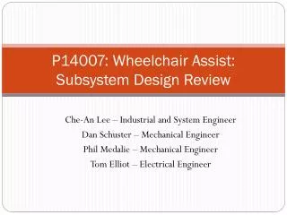
Midway Design Review Team 22: Driver Assist. Primary Solution. Our solution is to create a joystick that mechanically controls the steering wheel, brakes, and throttle The joystick will pivot horizontally allowing the driver to turn left and right.

E N D
Primary Solution • Our solution is to create a joystick that mechanically controls the steering wheel, brakes, and throttle • The joystick will pivot horizontally allowing the driver to turn left and right. http://img.gizmag.com/onehandeddriving.JPG?fit=max&h=670&w=770&s=4af0a21ce275fd7e9e9c78f8c92c344c
Block Diagram Control signal Joystick signal Feedback signal Power
MDR Deliverables • Have motor selected with correct output torque and speed (have gearing ratio required computed) • Have a wheel jacket prototype created and mounted on steering wheel base • Have control over motors movements • Have power circuit functioning to drive controller • Have a functioning brake and throttle prototype • Have a functioning battery recharger Note: Red font was original MDR deliverable
Individual Assignments for MDR Steve Cook: • Throttle • Brakes Sam Burke: • Gearing • Wheel Jacket • Controller Debugging Qingchuan Wu: • Power Supply • Motor Driver Design • Battery Charger Andrew Klinkowski: • Controller • Motor Driver Implementation
Motor Selection Requirements • Speed: 1.5rps • Torque: 6Nm Motor Specs • Speed: 4000RPM • Torque: .125Nm • Brushless DC
Gearing • A gearing ratio of 48 will allow us to have the outputted torque required, while staying within the speed limit. • .125Nm * GearRatio = 6Nm • GearRatio = 48 • Speed = (4000rpm/60)/48 = 1.38889 rps
Steering Wheel Jacket • In our prototype design a piece of plexiglass was used with a bike chain mounted to it using JB Weld. • The bike chain can be spun by the motor which spins the steering wheel
Brake Prototype • The brake stops the car and control reverse in the video game. • Includes: potentiometer, wire, and hand brake • Potentiometer sends a voltage reference between 0.58V to 4.5V depending on depression of hand brake • Higher voltage corresponds to harder braking • 10k Potentiometer is used to reduce power and maximize voltage reference swing.
Throttle Prototype • Throttle allow the driver to control the gas • Includes: potentiometer, wire, and throttle • Potentiometer send a voltage reference between 3.92V to 0Vdepending on position of the throttle • Lower the reference voltage corresponds to faster acceleration • 10k Potentiometer is used.
Power – Battery Charger Requirement • Charge external 12V NiMH battery from the cigarette port. 11- 14V input • Limit Charging current below 3A • Limit Charging voltage below 16V
Battery Charger • Used to charge external battery pack from 12V car battery
Power – Battery Charger Result • SEPIC topology charger
Power – Power Supply Requirement • Requirement • Provide regulated supply voltage 7.5V for controller • Provide 2 isolated voltages 12V for driving Mosfet • Implementations • Flyback converter • PI control on 7.5V output • Mutual inductance regulation on 12V outputs
Power – Power Supply • Requirement • Provide regulated supply voltage 7.5V for controller • Provide 2 isolated voltages 12V for driving Mosfet • Implementations • Flyback converter • PI control on 7.5V output • Mutual inductance regulation on 12V outputs
Power – Power Supply Result • Able to provide power to the controller and Mosfet Driver • Insufficient cross regulation due to the leakage inductance of the toroid
Motor Controller • An arduino is used to control the motor. • The arduino controls the frequency of the motors phases
Motor Driver • The driver amplifies the arduinos outputs to be used by the motor
Basic Motor Phase control U/V phase excitation A’ = 0 B’= 1 A = 0 B = 1 Flow of current
CDR Deliverables Steve Cook: • 3D print top half of the joystick • Install hand brake and throttle • Power supply PCB design Sam Burke: • Implementation of gear train • Mount functional motor to drive steering wheel • Controller PCB design Andrew Klinkowski: • Full control over DC motor at required spec of 1.5rps • 3D printed wheel jacket • Mount bike chain to wheel jacket Qingchuan Wu: • PCB printed charger • Charger optimization increased to 85% • Power supply rails well regulated
Motor Phase control- Buck (CDR) U/V phase excitation A’ = PWM B’= 1 A = 0 B = 1 Flow of current Normal PWM on PWM off
Motor Phase control- Boost (CDR) U/V phase excitation A’ = 0 B’= 1 A = PWM B = 1 Flow of current Normal PWM on PWM off