Download
1 / 37
380 likes | 601 Views
Lecture Note on Synchronous Optical Network (SONET). Telephony: Multiplexing. Telephone Trunks between central offices carry hundreds of conversations: Can’t run thick bundles! Send many calls on the same wire: multiplexing Analog multiplexing

E N D
Telephony: Multiplexing • Telephone Trunks between central offices carry hundreds of conversations: Can’t run thick bundles! • Send many calls on the same wire: multiplexing • Analog multiplexing • bandlimit call to 3.4 KHz and frequency shift onto higher bandwidth trunk • Digital multiplexing: convert voice to samples • 8000 samples/sec => call = 64 Kbps
Telephony: Multiplexing Hierarchy • Pre-SONET: • Telephone call: 64 kbps • T1 line: 1.544 Mbps = 24 calls (aka DS1) • T3 line: 45 Mbps = 28 T1 lines (aka DS3) • Multiplexing and de-multiplexing based upon strict timing (synchronous) • At higher rates, jitter is a problem • Have to resort to bit-stuffing and complex extraction => costly “plesiochronous” hierarchy • SONET developed for higher multiplexing aggregates • Use of “pointers” like C to avoid bit-stuffing
No Guaranteed Timing Synchronization Digital Telephony in 1984 Fiber Optic Transmission Systems DS1 M13 M13 DS1 DS1 Cross Connect • Switches • Leased Line Fiber DS3 Central Office M13 Central Office DS3 • Key System Aspects: • M13 Building Blocks • Asynchronous Operation • Electrical DS3 Signals • Proprietary Fiber Systems • Brute Force Cross Connect • AT&T Network/Western Electric Equipment DS1 Central Office
Digital Carrier Hierarchy (cont’d) • Multiplexing trunk networks: called “carrier” systems (eg: T-carrier): • allowed fast addition of digital trunk capacity without expensive layout of new cables • Time frames (125 us) and a per-frame bit in the T-carrier for synchronization => TDM • Each phone call (DS0) occupies same position in the frame • Overhead bits: error control • “robbed” bits in voice call for OAM information • Too many 0s => synch loss (max number = 15) • “yellow alarm”. 1s density etc => usable b/w = 7bits/frame => 56 kbps • Europe: E1; more streamlined framing & 2.048 Mbps • Variants: Concatenated T1, Un-channelized (raw) T1
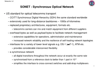
Digital Hierarchy (Cont’d) • 1980s: demand for bandwidth. But > T3s not available except in proprietary form • Fiber-optic interface for T3 was proprietary • Primitive online OAM&P capabilities (e.g: robbed bits…) • Fewer operators: interoperability/mid-span meet not critical • Changed dramatically after 1984 deregulation! • Public vs Private Networks: • Private: Customer operates networks (e.g: w/ private leased lines): developed from PBX & SNA • Public: Provider operates networks for subscribers • More public networks (e.g: X.25) outside US • Drivers of SONET: • IBM SNA/mainframes => hub-and-spoke networking • Increase of PCs => client-server & p2p computing => more demands on long-distance trunks • T-carrier evolution rate much slower than computing trends
Digital Hierarchy (Cont’d) • Digital streams organized as bytes (eg: voice samples, data) • Byte interleaving: (eg: 24 DS0 -> DS1) • service one byte from each input port into a transmission frame • Simple device: T1 mux a.k.a channel bank • Very convenient for processing, add-drop multiplexor (ADM) or Digital Cross-connect System (DCS) functions (fig 3.8/3.10) • ADM/DCS does both mux (“add”) and demux (“drop”) functions => need to do this with minimal buffering, fast/scalable processing • Bit-interleaving (eg: DS1 -> DS2 etc) • Cant use buffers to mask jitter! => bit stuffing • Partly because high speed memory was costly then! • “Plesiochronous hierarchy” => harder to ADM/DCS because full de-stuffing/de-multiplexing necessary before these functions • DS3s used to be muxed using proprietary optical methods (eg: M13 mux): SONET solves all these problems
Post-AT&T Divestiture Dilemmas • Switches • Leased Line • LAN Services • Data Services Different Carriers, Vendors DS1 M13 Internal DS3 Cross Connect • Needs: • Support Faster Fiber • Support New Services • Allow Other Topologies • Standardize Redundancy • Common OAM&P • Scalable Cross Connect Support Other Topologies, Protect Fibers
The SONET Standards Process Divestiture CCITT Expresses Interest in SONET SONET/SDH Standards Approved Exchange Carriers Standards Associate (ECSA) T1 Committee Formed British and Japanese Participation in T1X1 ANSI T1X1 Approves Project CCITT XVIII Begins Study Group CEPT Proposes Merged ANSI/CCITT Standard Bellcore Proposed SONET Principles To ANSI T1X1 1984 1985 1986 1987 1988 SONET Concept Developed By Bellcore • >400 Technical Proposals • Rate Discussions AT&T vs. Bellcore • (resolved w/ virtual tributary concept) • International Changes For Byte/Bit Interleaving, Frames, Data Rates • Phase I, II, III Separate APS, etc. • ITU’s SDH initiative… US T1X1 Accepts Modifications ANSI Approves SYNTRAN
SONET Standards Story • SYNTRAN: pre-divestiture effort, no pointer concept. • SONET: primarily US (divestiture) driven • AT&T vs Bellcore debate: 146.432 Mbps vs 50.688 Mbps: compromise at 49.94 Mbps • Virtual tributary concept to transport DS-1 services • 1986: CCITT (ITU) starts own effort (SDH) • June 1987: change SONET from bit-interleaved to byte-interleaved; and rate from 49.92 to 51.84 Mbps • Phased rollouts: • 1988 = Phase 1: signal level interoperability • Phase II: OAM&P functions: embedded channel & electrical I/f specification, APS work initiated • Phase III: OSI network management adopted • Seamless worldwide connectivity (allowed Europe to merge its E-hierarchy into SDH)
1. Standard multiplexing using multiples of 51.84 Mbps (STS-1 and STS-N) as building blocks 2. Optical signal standard for interconnecting multiple vendor equipment 3. Extensive OAM&P capabilities 4. Multiplexing formats for existing digital signals (DS1, DS2 etc) 5. Supports ITU hierarchy (E1 etc) 6. Accommodates other applications: B-ISDN etc SONET: Achievements
SONET Lingo • OC-N: Optical carrier Nx51.84 Mbps • Approximate heuristic: bit rate = N/20 Gbps (e.g: OC-48 => 48/20 = 2.4 Gbps) • Overhead percentage = 3.45% for all N • OC signal is sent after scrambling to avoid long string of zeros and ones to enable clock recovery • STS-N: Synchronous Transport Signal (electronic equivalent of OC) • Envelope: Payload + end-system overhead • Synchronous payload envelope (SPE): 9 rows, 87 columns in STS-1 • Overhead: management OAM&P portion • Concatenation: “un-channelized” (envelope can carry “super-rate” data payloads: eg: ATM): Eg: OC-3c • Method of concatenation different from that of T-carrier hierarchy…
SONET Multiplexing Possibilities • Asynchronous DS-3 • Virtual Tributaries for DS1 etc • STS-3c for CEPT-4 and B-ISDN STS-1s are mutually synchronized irrespective of inputs
STS-1 Frame Format 90 Bytes Or “Columns” 9 Rows Small Rectangle =1 Byte • Two-dimensional frame representation (90 bytes x 9 bytes)… • Frame Transmission: Top Row First, Sent Left To Right • Time-frame: 125 ms/Frame • Frame Size & Rate: • 810 Bytes/Frame * 8000 Frames/s * 8 b/byte= 51.84 Mbps • For STS-3, only the number of columns changes (90x3 = 270) STS = Synchronous Transport Signal
Section Overhead (SOH) Path Overhead (POH): Floating => can begin anywhere Line Overhead (LOH) STS-1 Headers 90 Bytes Or “Columns” 9 Rows Line + Section overhead = Transport Overhead (TOH)
Path Sections • Section Termination (STE) Line • Line Termination (LTE) • Path Termination (PTE) SONET Equipment Types PTE Repeaters SONET End Device - I.e. Telephony Switch, Router PTE
Headers: Section Overhead (SOH) A1 =0xF6 A2 =0x28 J0/Z0 STS-ID Rcv SOH Xmt SOH B1 BIP-8 E1 Orderwire F1 User D1 Data Com D2 Data Com D3 Data Com • Selected Fields: • A1,A2 - Framing Bytes • BIP-8 - Bit Interleaved Parity • F1 User - Proprietary OAM Management • Section Overhead • 9 Bytes Total • Originated And Terminated By All Section Devices (Regenerators, Multiplexers, CPE) • Other Fields Pass Unaffected
Headers: Line Overhead (LOH) H1 Pointer H2 Pointer H3 Pointer Act B2 BIP-8 K1 APS K2 APS Xmt LOH Rcv LOH D4 Data Com D5 Data Com D6 Data Com Rcv SOH Xmt SOH Xmt SOH Rcv SOH D7 Data Com D8 Data Com D9 Data Com D10 Data Com D11 Data Com D12 Data Com S1 Sync M0 REI E1 Orderwire • Line Overhead • 18 Bytes Total • Originated And Terminated By All Line Devices (Multiplexers, CPE) • LOH+SOH=TOH (Transport OH) • Selected Fields: • H1-3 - Payload Pointers • K1, K2 - Automatic Protection Switching • D4-D12 - 576 kbps OSI/CMIP
b Floating Payload: SONET LOH Pointers SPE is not frame-aligned: overlaps multiple frames! Avoids buffer management complexity & artificial delays Allows direct access to byte-synchronous lower-level signals (eg: DS-1) with just one frame recovery procedure
SPE: Synchronous Payload Envelope • Defined Payloads • Virtual Tributaries (For DS1, DS2) • DS3 • SMDS • ATM • PPP … • Synchronous Payload Envelope • Contains POH + Data • First Byte Follows First Byte Of POH • Wraps In Subsequent Columns • May Span Frames • Up To 49.536 Mbps for Data: • Enough for DS3
Headers: Path Overhead (POH) J1 Trace PTE STE PTE B3 BIP-8 • Selected fields: • BIP-8 - Parity • C2 - Payload Type Indicator • G1 - End End Path Status Frame N Frame N Frame N+1 C2 Sig Label Frame N+1 G1 Path Stat • Path Overhead • H1,H2 fields of LOH points to Beginning of POH F2 User H4 Indicator • POH Beginning Floats Within Frame Z3 Growth • 9 Bytes (1 Column) Spans Frames Z4 Growth • Originated And Terminated By All Path Devices (I.e. CPE, Switches) • End-to-end OAM support Z5 Tandem
Accommodating Jitter Positive Stuff Negative Stuff • To Shorten/Lengthen Frame: • Byte After H3 Ignored; Or H3 Holds Extra Byte • H1, H2 Values Indicate Changes - Maximum Every 4 Frames • Requires Close (Not Exact) Clock Synch Among Elements
Clock Synchronization BITS BITS • Level 1: 10-11 • Level 2: 1.6x10⁻⁸ • Level 3: 4.6x10⁻⁶ • Level 4: 32x10-6 PTE Primary Reference Backup Reference • Building Integrated Timing System • Hierarchical Clocking Distribution • Normally All Synch’d To Stratum 1 (Can Be Cesium/Rubidium Clock) • Dedicated Link Or Recovered • Fallback To Higher Stratum In Failure (Temperature Controlled Crystal) BITS PTE
STS-N Frame Format 90xN Bytes Or “Columns” N Individual STS-1 Frames Examples STS-1 51.84 Mbps STS-3 155.520 Mbps STS-12 622.080 Mbps STS-48 2.48832 Gbps STS-192 9.95323 Gbps • Composite Frames: • Byte Interleaved STS-1’s • Clock Rate = Nx51.84 Mbps • 9 colns overhead Multiple frame streams, w/ independent payload pointers Note: header columns also interleaved
STS-N: Generic Frame Format STS-N STS-1
STS-Nc Frame Format 90xN Bytes Or “Columns” Transport Overhead: SOH+LOH • Concatenated mode: • Same TOH Structure And Data Rates As STS-N • Not All TOH Bytes Used • First H1, H2 Point To POH • Single Payload In Rest Of SPE • Accommodates FDDI, E4, data Current IP over SONET technologies use concatenated mode: OC-3c (155 Mbps) to OC-192c (10 Gbps) rates a.k.a “super-rate” payloads
Virtual Tributaries (Containers) • Opposite of STS-N: sub-multiplexing • STS-1 is divided into 7 virtual tributary groups (12 columns ea), which can be subdivided further • VT groups are byte-interleaved to create a basic SONET SPE • VT1.5: most popular quickly access T1 lines within the STS-1 frame • SDH uses the word “virtual containers” (VCs)
Virtual Tributaries: Pointers • VT payload (a.k.a VT SPE) floats inside the VT • One more level of pointer used to access it. • Can access a T1 with just two pointer operations • Very complex to do the same function in DS-3 • Eg: accessing DS0 within DS-3 requires FULL de-multiplexing: a.k.a stacked multiplexing or mux-mountains!
Practical SONET Architectures Today: multiple “stacked” rings over DWDM (different s)
SONET Network Elements D+R MN MN ADM DCC TM DS1s D+R MN MN D+R DS1s Nonstandard, Functional Names TM: Terminal Mux: (aka LTE: ends of pt-pt links) ADM: Add-Drop Mux DCC: Digital Cross Connect (Wideband and Broadband) MN: Matched Node D+R: Drop and Repeat
Digital Cross Connects (DCS) • Cross-connects thousands of streams under software control (replaces patch panel) • Handles performance monitoring, PDH/SONET streams, and also provides ADM functions • Grooming: • Grouping traffic with similar destinations, QoS etc • Muxing/extracting streams also • Narrow-/wide-/broad-band and optical crossconnects
Topology Building Blocks ADM ADM 2 Fiber Ring 4 Fiber Ring DCC ADM DCC ADM Each Line Is Full Duplex Each Line Is Full Duplex ADM ADM ADM ADM DCC ADM DCC ADM ADM ADM Uni- vs. Bi- Directional All Traffic Runs Clockwise, vs Either Way
APS ADM ADM ADM ADM ADM ADM Line Protection Switching Path Protection Switching Uses TOH Trunk Application Backup Capacity Is Idle Supports 1:n, N=1-14 Uses POH Access Line Applications Duplicate Traffic Sent On Protect 1+1 • Automatic Protection Switching • Line Or Path Based • Revertive vs. Non-Revertive • Mechanism For Intentional Cutover • Restoration Times ~ 50 ms • K1, K2 Bytes Signal Change • Common Uses: 2 Fiber UPSR or ULSR, 4 Fiber BPSR