Download
1 / 43
430 likes | 447 Views
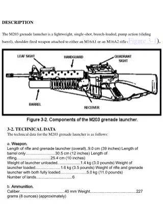
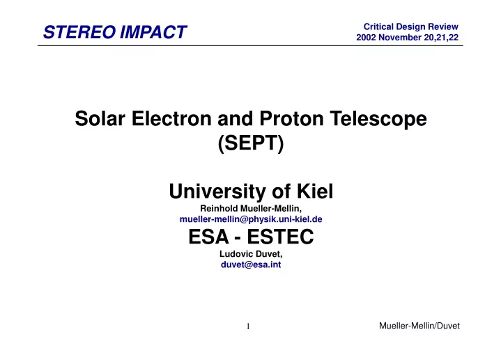
Solar Electron and Proton Telescope (SEPT) University of Kiel Reinhold Mueller-Mellin, mueller-mellin@physik.uni-kiel.de ESA - ESTEC Ludovic Duvet, duvet@esa.int. SEPT System Description. Consists of two dual double-ended particle telescopes Measures electron spectrum between 20 and 400 keV

E N D
Solar Electron and Proton Telescope (SEPT)University of KielReinhold Mueller-Mellin, mueller-mellin@physik.uni-kiel.deESA - ESTECLudovic Duvet, duvet@esa.int Mueller-Mellin/Duvet
SEPT System Description • Consists of two dual double-ended particle telescopes • Measures electron spectrum between 20 and 400 keV • Measures proton spectrum between 60 and 7000 keV • Emphasis on clean separation between electrons and protons • Uses magnet to deflect electrons < 400 keV • Uses foil to stop protons < 400 keV • Provides anisotropy information on non-spinning S/C • In-ecliptic: towards and away from the Sun • Off-ecliptic: from North and from South Mueller-Mellin/Duvet
SEPT Telescope Schematic Magnet 2 PIPS with guard Parylene foil Mueller-Mellin/Duvet
SEPT Performance Requirements STEREO Configuration Change Request issued, June 18, 2002 Mueller-Mellin/Duvet
SEPT Interfaces to S/C • Mechanical • SEPT-E mounted directly to S/C +Y panel • SEPT-NS mounted on bracket to S/C +Z panel • Thermal • SEPT-E and -NS mounted with thermal isolation • Use op and non-op heaters • Use MLI and thermal paint • Electrical • Only S/C actuator power lines for 4 pin-pullers • No direct power, telemetry, telecommand interface with S/C Mueller-Mellin/Duvet
SEPT Resources Mueller-Mellin/Duvet
SEPT Responsibilities Mueller-Mellin/Duvet
SEPT Controlling Documents • SEPT Mechanical Interface Control Drawings, Sep. 2002 • Particle Detector Front End (PDFE) data sheet, Nov. 2000 • SEPT FPGA data sheet, June 2002 • SEPT Operation Control and Data Processing Requirements, Oct. 2002 • SEPT Level 1 Data Format, Oct. 2002 • SEPT Electronics Product Assurance Plan, July 2002 • SEPT Parts List, Oct. 2002 • SEPT Materials and Processes List, Sep. 2002 • SEPT MS Project 2000 Schedule, Sep. 2002 • SEPT-SEP_Central Interface Control Document (STEREO-CIT-010.A) • Statement of Work for IMPACT, Dec. 2001 Mueller-Mellin/Duvet
SEPT History • IMPACT PDR, Request for Actions • PDR RFA #13: SEPT Magnetic Emissions • Closed by way of far-field measurement of SEPT prototype magnets by MAG PI Mario Acuna, GSFC, May 14/15, 2002. • PDR RFA #29: Glint onto SEPT Detectors • Closed by way of UV lamp test at Univ. of Kiel, Apr. 2002, and additional 50 nm Al layer vacuum-deposited on PIPS detectors at Canberra Company, June 2002. • SEPT Door Peer Review • Held on Sep. 23, 2002. A total of 13 Action Items generated, 3 of which are closed, 10 are being worked on. Mueller-Mellin/Duvet
SEPT Door Review (09/23/02) Mueller-Mellin/Duvet
Design details: SEPT top view Mueller-Mellin/Duvet
Design details: SEPT Front View SEPT Side View Mueller-Mellin/Duvet
Design details: SEPT Cover mechanism Cover in open position, pinpuller in open and closed position Mueller-Mellin/Duvet
Design details: SEPT electronics block diagram Mueller-Mellin/Duvet
Stack configuration Analog board: side 1 Digital board: side 1 Stack configuration Analog board: side 2 Digital board: side 2 Design details: SEPT electronics boards • 3 boards: Analogue Board / Digital Board / EMI shield (not represented) 66.6 mm Bread board Mueller-Mellin/Duvet
Design details: SEPT electronics boards Ground stud MDM 31 Mueller-Mellin/Duvet
Design details: SEPT electronics specifications • Digital board: FPGA + SRAM + Filtering + Power supply switching + MDM 31 pins + temperature sensor. • Analog board: PDFE (Particle Detector Front End) + test pulse generator + housekeeping. • PDFE: ASIC (4 per SEPT unit) • Power supply: • 5.6 V analogue, 5.3 V digital, 2.6 V digital (all +/- 5 %) • - 80 Volt for SSD bias • switching of 5.6 V analogue and 5.3 digital controlled by FPGA (LU protection) • Temperature measurement (AD590) for operational heater in HK flow (1 minute resolution). S/C controlled temperature sensor routed from the sensor head through the E-Box to SEP Central. Mueller-Mellin/Duvet
SEPT-NS Surv & Op heaters SEPT-E Surv & Op heaters SEPTNS-P1 SEPTNS-J1 9 6 2.13m on S/C A, 3.48m on B SEPTE-P1 SEPTE-J1 9 6 SEPTNS-J3 SEPTNS-P3 31 SEPTE-J3 SEPTE-P3 37 SEP Central Electronics Box 31 SEP-P9 SEP-P7 SEPTNS-J2 SEP-J9 SEP-J7 SEPTNS-P2 Power/data/bias SEPTE-J2 SEPTE-P2 Power/data/bias 37 0.94m on S/C A, 2.44m on B MDM connector pair D connector pair Design details: SEPT electrical interface with SEP Mueller-Mellin/Duvet
Design status: SEPT Sensor • Conceptual design • All drawings finished. • Door mechanism drawings submitted 27-JUN-02. • Housing • Fabrication EM started. • Ring mount for Parylene foil machined, Alodine surface treatment applied. • Parylene foil specified, fabrication ordered, expected delivery JAN-03. • Parts of sensor housing currently being machined. Several weeks delay. • Demonstration model for E-box housing delivered to ESTEC. Fabrication of EM started. • Pin-pullers ordered, expected delivery date OCT-02, not yet received. • Detector system • Prototype detector stack received, incoming inspection passed, one of 6 coax cable broken (during handling) and repaired. Failure cause identified: undue bending, poor stripping. Preventive action taken. • Detector assembly for EM and FM on halt due to triax cable problem. Triax cable not accepted by IMPACT project manager (too heavy). Coax cable solution made possible by change in grounding concept: SEPT sensor is now on analog ground. • New supplyer for cable RG 178 (AXON) and connectors SSMC (AEP) identified. Quotation received. Cable assembly ordered. Delivery date: 29-NOV-02. Mueller-Mellin/Duvet
Design status: SEPT Sensor (continued) • Magnet system • Test mount for prototype magnet ready. • Magnetic interference test at GSFC passed. • EM and FM magnets assembled at Vacuumschmelze. Delayed by some weeks. New delivery date confirmed: 11-NOV-02. • Mathematical model • Monte Carlo GEANT simulation improved. • Technical Assistance Agreement • TAA signed Apr. 8, 2002 Mueller-Mellin/Duvet
Design status: SEPT Sensor (continued) • SEPT structural model (SM) • Used to design EM • Used to demonstrate cover release mechanism • Contains mostly Lab-Model but some EM elements Mueller-Mellin/Duvet
Design status: SEPT electronics • Two breadboards have been manufactured: • BB1: first release of the FPGA • BB2: second release of the FPGA • BB1 has been used for integration with detector (26th-29th August, ESTEC) • BB2 is being investigated (KTH Institute, Sweden) • TAA signed Aug. 2, 2002 • FPGA: 3rd design including modifications for the design has been delivered (if no further modification, this design is the FM). • PDFE redesign in progress (minor changes only for reuse in future projects). • GSE Power supply is specified. • PDFE Characterization Test Bench is being specified (but needed for EM) • Present GSE software compatible with 2nd version of the FPGA, next version is being implemented (minor changes) . Mueller-Mellin/Duvet
Design status: SEPT electronics (continued) GSE (version 2) screen snapshot Mueller-Mellin/Duvet
Design status: SEPT electronics (continued) • EM : • Layout complete • Commercial FPGA • Engineering model SRAM (Honeywell) • Possibility to have crystal or clock oscillator for the PDFE • FPGA design 3rd version • FPGA crystal commercial • PDFE 1st generation (pinout fully compatible with the new design) • Grounding „flexibility“ • Manufacturing phase • To be done for flight model • Layout of the FM will necessitate minor changes wrt to EM • Crystal for FPGA • Retained solution for the PDFE clock • Others depending on EM performances? • Filtering/grounding updates if needed Mueller-Mellin/Duvet
Design status: SEPT electronics (continued) • Parts/Materials status • Parts list has been agreed to at the Parts Control Board, with some recommended additional screening of two of the parts being investigated at UCB (October 3rd 2002) • FPGA flight parts have been delivered • SRAM flight parts delivery is pending • Other parts delivered at 90 % at the time of delivery of the CDR data package. • PDFE flight parts delivered end of March 2003 • Screening flow approved • No screening has been started yet. • Radiations tests not started at the time of delivery of the CDR data package (delay due to late delivery of test PCBs) • No source identified for 18 MHz crystal (FPGA). Mueller-Mellin/Duvet
SEPT Performance Issues Monte-Carlo-Simulation Red track from magnet side: 500 keV electrons Red track from foil side: 300 keV electrons Blue track from both sides: 400 keV protons Magnet PIPS Detector Foil Mueller-Mellin/Duvet
SEPT performance issues (continued) • Integration of detector + breadboard electronics lead to satisfying results Bi207 source Detector Mueller-Mellin/Duvet
SEPT performances issues Discriminator level=80 keV Front detector Coinci. detector Detector noise alone FWHM ~ 7 keV With lab. Electron. FWHM ~ 7 keV With Breadboard FWHM ~ 26 keV Electronic noise FWHM ~ 25 keV Cross-talk rings (1 bin =8.59 keV) (48 hour accumulation) Mueller-Mellin/Duvet
SEPT performance issues (continued) • Noise level issue: • The breadboard was not optimized for real measurements, more a functional board. • The trimming of the PDFEs (bias voltages and bias currents) had not been optimized. For the flight parts, a “dedicated” datasheet will be attached to each PDFE with the optimum parameters (PDFE Characterization Test Bench). • The noise has been identified as coming mainly from digital coupling between PDFEs and not within a PDFE. To cure this problem the number of layers on the analog board has been increased and the grounding improved. Mueller-Mellin/Duvet
SEPT EMC • Internal grounding designed to avoid coupling between the 4 PDFEs. • Filtering/regulation: • ‘Pi filter’ on each power line (33 uH, 10 uf) • RCR filter on SSD bias voltage (5 MOhm, 3nf) • Post regulation on 5 Volt analogue (<1% accuracy) • Connection between E-Box and detector via coaxial connectors and not triaxial connectors. • Bias voltage brought from MDM31 to Analog Board via a coaxial cable. • AGND, DGND, BIAS_ret, MSTR_RTN (+50 Ohm), SUB_RTN connected together at a unique point, ‘STAR’, connected itself to S/C structure via the ground stud. The possibility to have additional AGND and DGND connections close to each PDFE will be investigated on the EM. Mueller-Mellin/Duvet
SEPT EMC Detector housing NB: Are not represented: - coaxial cable for S/C temperature sensor - J1 connector - Coax cable for SSD bias X 12 SSD Sensor structure Coaxial cable E-box Analog board mid layer is connected to “STAR” AB SSMC bulkhead (backshell connected to E-box housing) Backshell connection Main harness shield Digital signal inner shield MMCX connector (backshell connected to AGND) EMI shield J2 To LVPS star DB “STAR” To Sep chassis Off board connector Ground stud S/C Insulator Mueller-Mellin/Duvet
SEPT Contamination Mueller-Mellin/Duvet
FPGA +5.6V A Over current sense Latchup detection (prog. Timer) FAULT +5.3V D Over current sense Latchup detection (prog. Timer) FAULT Environmental compatibility and issues • Radiations: • FPGA is rad-tolerant + latchup immune. • SRAM is rad-tolerant + latchup immune. • Plastic parts: total dose and heavy ions tests at ESTEC (+ Louvain-La-Neuve) • LU for non LU immune parts is addressed by the following mitigation technique (SET handled by prog. Timer): MAX892 (for each telescope) Mueller-Mellin/Duvet
Risks issues and mitigations • Non standard part qualification failure: • PDFE: • The production of the flight parts will be done for the 1st generation and the 2nd generation design. • Screening will be performed on second generation after functional tests. If negative, screening will be performed on 1st generation. • TID preliminary tests on 1st design compliant with the 5-year extended mission requirement. • Plastic Encapsulated Microcircuits: • A back up part has been identified for all of them except for MAX892 • Critical parts (MAX892, ADP3300): qualification failure may lead to delay. • Good confidence level for MAX892 (existing tests). • Non critical parts: the screening is done at ESTEC which gives much more flexibility. Mueller-Mellin/Duvet
Manufacturing • SEPT Electronics • PDFE screening: TBC • Plastic part screening: TBC • Other tests on parts: TBC • EM PCB: Darco (Be) • FM PCB: Printca (Dk) • PCB/parts assembly: RSSD Flight Instrument Support Group (FISG) and the company Netronics (NL) • SEPT Sensor & Housing: • Housing: Univ. of Kiel • Detector stack: Canberra Semiconductor N.V. (Belgium) • Magnet system: Vacuumschmelze (Germany) • Parylene foil: Lebow Company (USA) • Coax cables: Axon Kabel GmbH (Germany/France) • Integration and test: Univ. of Kiel Mueller-Mellin/Duvet
SEPT Verification Plan For details see IMPACT Verification/Validation Plan Mueller-Mellin/Duvet
SEPT Environmental Test Plan (mechanical) Note: Protoflight Approach. For details see IMPACT Environmental Test Plan Mueller-Mellin/Duvet
SEPT Environmental Test Plan (magnetics, thermal) Note: Protoflight Approach. For details see IMPACT Environmental Test Plan Mueller-Mellin/Duvet
SEPT Schedule • PDFE flight parts delivery to ESTEC: end of March 2003. • Engineering Model: • Delivery of electronic boards to Kiel: 20th January 2003 • SEPT integration and tests (Kiel) : 20th January 2003 till 14th March 2003 • Hardware/software interface tests with SEP-DPU: 10th June 2003, 1 week • Flight models: • Schematics update: 6th January 2003, 6 weeks. • FM1 (SEPT-E=PF) • Delivery of electronics to Kiel 18/07/03 • Integration & test, Radioactive sources, Vib., TV/TB 21/07/03, 55 days • Delivery to Caltech 08/10/03 • FM2: • Delivery of electronics to Kiel 15/08/03 • Integration & test , Radioactive sources, Vib., TV/TB 18/08/03, 37 days • Delivery to Caltech 09/10/03 • FS delivery of electronics to Kiel 12/09/03 Mueller-Mellin/Duvet
SEPT Transport issues • No active purge and no active temperature control during transport. SEPT will be placed in a bag, the bag will be flooded with dry nitrogen gas, and sealed. • ESD protection: wrap in ESD protection bag, dry, fragile marking, ESD protection marking. • Export documentation. Mueller-Mellin/Duvet
SEPT Open issues / concerns • Noise level. • Component sources still open (especially crystal). Mueller-Mellin/Duvet