Download
1 / 58
580 likes | 589 Views
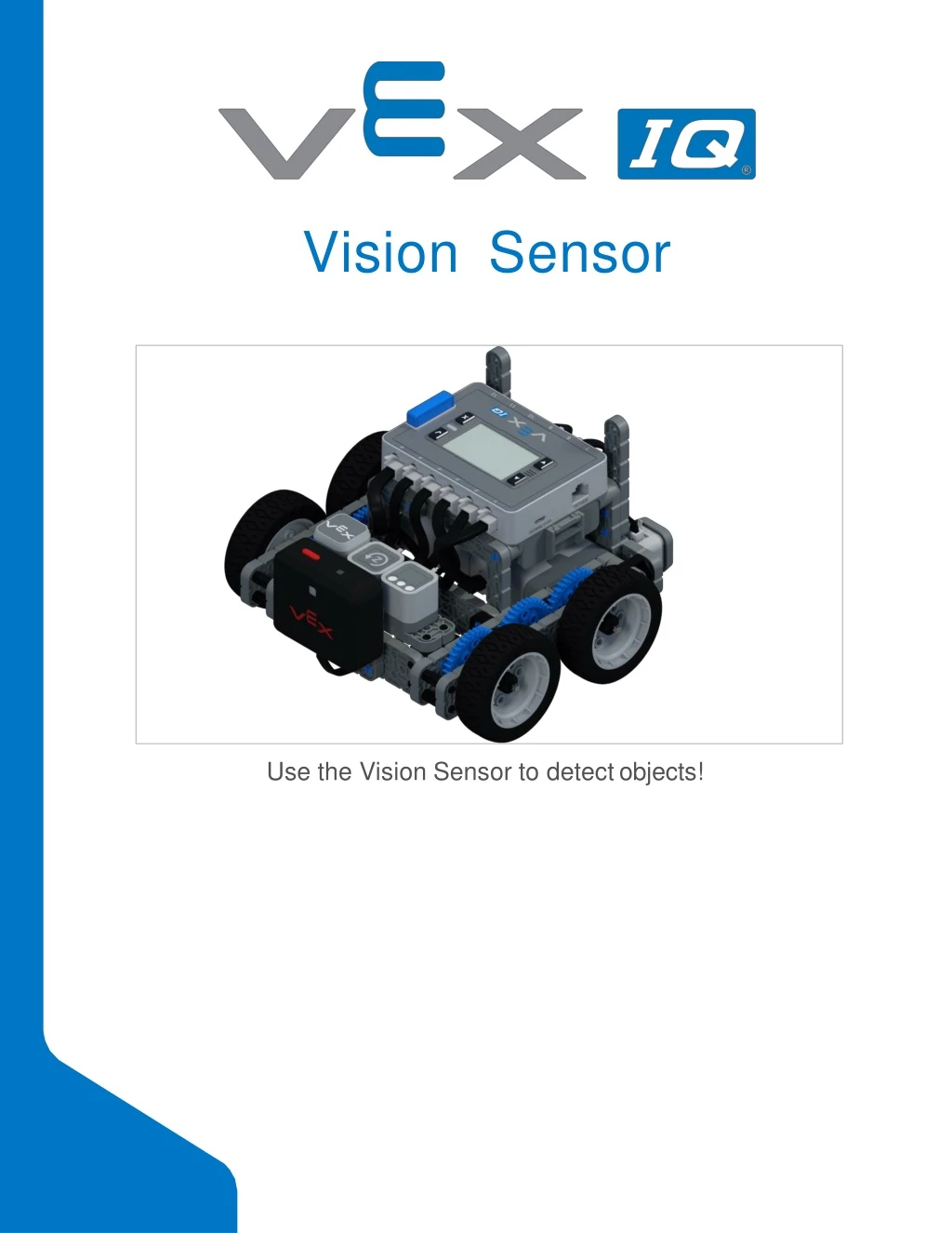
Visi o n S e n s or. Use the Vision Sensor to detect objects!. Discover new hands-on builds and programming opportunities to further your understanding of a subject matter. The Completed Look of the Build. The completed Autopilot robot build.

E N D
VisionSensor Use the Vision Sensor to detectobjects!
Discover new hands-on builds and programming opportunities to further your understanding of a subjectmatter.
The Completed Look of the Build The completed Autopilot robotbuild. This robot is designed so that it can be built quickly and drive around either autonomously or with the Controller in a short amount oftime.
Steps 1-6 will be repeated for steps 7–12, so it’s possible to make both at once. Count all pieces before starting your build and have them readilyavailable.
When adding the 4x Pitch Shaft, twist the pitch shaft to check for tension while turning. If it spins freely, it is not properly inserted into the motor.
Make sure the gears fit together properly before locking the Beam inplace. After attaching the wheels, twist the wheel that has the shaft going into the motor. If the wheel spins freely and without tension, the 4x Pitch Shaft has slipped out ofplace.
When adding the 4x Pitch Shaft, twist the pitch shaft to check for tension while turning. If it spins freely, it is not properly inserted into the motor.
Make sure the gears fit together properly before locking the Beam inplace. After attaching the wheels, twist the wheel that has the shaft going into the motor. If the wheel spins freely and without tension, the 4x Pitch Shaft has slipped out of place.
The highlighted blue numbers placed in gear shapes represent the assemblies completed from those specific steps.
Ensure the Smart Radio and Robot Battery are inserted before attaching the Brain to the rest of theassembly. Steps 29-30, when you attach the Smart Cables, make sure they are tucked away so as to not block the Smart Sensors. The orange arrows indicate to turn the robotaround.
AddingtheVisionSensor After the Autopilot has been assembled, use the building instructions below to add the Vision Sensor.
Exploration • Now that the build is finished, explore and see what it can do. Then answer this question in your engineeringnotebook. • Predict and describe how the Autopilot robot’s behavior would change if the shaft in Step 2 of the robot Build Instructions was not inserted into the motor on one side of the robot, provide a diagram and a discussion of what purpose the rubber shaft collar on the motor shaft serves with yourdescription.
Test your build, observe how itfunctions, and fuel your logic and reasoning skills through imaginative, creativeplay.
What is a Vision Sensor? Description The Vision Sensor allows your robot to collect visual data from a live feed. A live feed is a streaming transmission of what a video camera is capturing. The Vision Sensor is like a smart camera that can observe, select, adjust, and store colors and objects that appear in its visualfield. Vision Sensor 276-4850 • Capabilities: • This sensor can be used for recognizing colors and colorpatterns. • This sensor can be used to follow anobject. • This sensor can be used to collect information about theenvironment. • The Vision Sensor allows the robot to use visual input data from its environment. The project can then determine how the visual input data should affect the robot's behavior. For example, the robot could perform actions (output) such as spinning motors or displaying results on the LCD screen. • The Vision Sensor can also capture a snapshot of what is in front of it and analyzeit
according to what the user is asking. For example, a user can gather data from the snapshot such as, what color is the object? Is there an object detected at all? How large is the object (width andheight)? The robot can then make decisions based off of this data. The partial example project below shows how this is done. In this first part of the example project, the robot will print "Blue Object Found" if a blue object is detected and "No Blue Object" otherwise. That is the first of three decisions within the example project but the second and third decisions are not shown here.
Using the Vision Sensor The Builder in each group should get the hardware required. The Recorder should get the group’s engineering notebook. The Programmer should open VEXcode IQBlocks. Hardware/SoftwareRequired: This activity will give you the tools to use the VisionSensor. You can use the Help information inside of VEXcode IQ Blocks to learn about the blocks. For guidance in using the Help feature, see the Using Helptutorial. • 1. Preparing for theactivity • Before you begin the activity, do you have each of these items ready? The Builder should check each of thefollowing: • Are all the motors and sensors plugged into the correctport? • Are the smart cables fully inserted into all of the motors andsensors? • Is the Brain turnedon? • Is the batterycharged?
2. Open an ExampleProject. • VEXcode IQ Blocks contains many different example projects. You’ll use one of them in this exploration. For help and tips on using example projects, check out the Using Examples and Templatestutorial. Then, open the Detecting Objects exampleproject. • The Programmer should complete the following steps: • Open the Filemenu. • Select OpenExamples. • Use the filter bar at the top of the application and select"Sensing." • Select and open the Detecting Objects exampleproject. • Save your project as DetectingObjects. • Check to make sure the project name Detecting Objects is now in the window in the center of thetoolbar. • For addition help, view the Use Example Projects and Templates tutorialvideo.
3. Configuring and Using the VisionSensor • Begin by watching the Configuring the Vision Sensor tutorialvideo. • Next, configure the Vision Sensor for three colored objects: red, green, andblue. • Have the Programmer open the previously saved Detecting Objects exampleproject. • What is this project actually doing? Predict what the Autopilot will do and have the Recorder write down the predictions in your engineeringnotebook. • Have the Driver Download and Run the project. Have the Builder place different colored objects in front of the Vision Sensor and observe the robot's behavior. Have the Recorder record in your engineering notebook how your prediction was different orcorrect
compared to what you actually observed from theproject. For additional help, view the Download and Run a Project tutorialvideo. 4. Tuning the VisionSensor • Often times an object is configured to be recognized by the Vision Sensor in one environment, for example, in a classroom. When the Vision Sensor is then taken into a different environment such as a competition setting, the object may not be recognized by the Vision Sensor. This is often due to a change in lighting after the Vision Sensor has already been configured. To solve this problem, you may have to tune your VisionSensor. • Begin by watching the Tuning the Vision Sensor tutorialvideo. • Next, Tune the Vision Sensor for the three colored objects: red, green, andblue. • Have the Programmer open the previously saved Detecting Objects exampleproject. • How will tuning the Vision Sensor affect how well it can detect objects? Have the Builder take the Autopilot to a different part of the room with more or lesslight.
Have the Driver Download and Run the project. Have the Builder place different colored objects in front of the Vision Sensor and observe the robot's behavior. Have the Recorder document in your engineering notebook how well the Vision Sensor detects objects. Does the Vision Sensor need tuned after it changedlocations? • For additional help, view the Download and Run a Project tutorialvideo. • Tune the Vision Sensor as necessary. Test the Vision Sensor after it has been tuned to determine if it can detect objects better and make adjustments asneeded.
Become a 21st century problem solver by applying the core skills andconcepts you learned to otherproblems.
PerceptionwithSelf-Driving Vehicles A self-driving vehicle with an array ofsensors Perception with Self-DrivingVehicles Self-driving vehicles use a wide array of sensors to perceive their surroundings, on-board computers to combine and process the data from all of those sensors, and one or more motors to safely move the vehicle along the road using AI (artificial intelligence). Self-driving vehicles often make use of high resolution cameras to be able to recognize things such as pedestrians, road signs, and other vehicles. Vision data from the cameras is often combined with sensors that use lasers to measure distance between the vehicle and other objects. This allows the on-board computers to make decisions based on what types of objects are in their environment, and how far away each objectis.
CompetitionConnection: Crossover VRC 2016-2017 CrossoverField Robot Capabilities The 2016 - 2017 VEX Robotics Competition game Crossover required players to place their colored Hexballs in their scoring zones. There were 28 Hexballs in total: 14 of each color (blue and orange) per team. Points were earned by placing the team's correctly colored Hexball in their goal zone. Although it was illegal to use a Vision Sensor in a VEX IQ Robotics Competition in 2016-2017, you can imagine that competition teams could have benefited from using the Vision Sensor to detect the team-specific colored Hexball. It would be easier for the robot to pick up the correctly colored Hexball during the autonomous period if the robot was programmed to move towards and grab a certain colored object. If the robot selects the incorrect colored Hexball during the Auton period, there is a possibility that the robot would not score as many points. Similarly, for the Driving Skills Challenge, it may be hard for teams to manually line up the robot enough to place the Hexball in the goal. The Vision Sensor could be used to align the robot more accurately. Thus, skilled teams would program the robot to use the Vision Sensor to detect Hexballs and align the robot properly in order to place the Hexballs into thegoals.
Is there a more efficient way to come to the same conclusion? Take what you’ve learned and try to improveit.
PreparefortheVisionData Challenge The Vision Sensor's Sensing Blocks VEXcode IQ Blocks has Sensing blocks for the Vision Sensor. The first two you already used in the Play section to take a snapshot and to check if the objectexists. In the figure below, you see that the snapshot block captured the GREENBOX snapshot. The object, GREENBOX, was identified in the snapshot and so the answer of whether it exists is TRUE. Let's look at these other Sensing blocks and what their values tell us. • The object count block tells us how many GREENBOX objects are in the snapshot. Here, there is only 1detected. • The center X value tells us whether the GREENBOX object is to the left or right of the robot's center point. Remember, the Vision Sensor is mounted in the middle of the front of the robot and so the snapshot's view is the robot'sview. • If center X is greater than 157.5, the object is to the right of the robot's centerpoint. • If center X is less than 157.5, the object is to the left of the robot's centerpoint. • The center Y value tells us whether the GREENBOX is higher or lower than the robot's centerpoint.
If center Y is greater than 105.5, the object is lower than the robot's centerpoint. • If center Y is less than 105.5, the object is higher than the robot's centerpoint. • The width and height values tell us how close the GREENBOX is to therobot. • o The same-sized object will be larger in width and height as it gets closer to therobot. • How are the center X and center Y valuescalculated? • The values are calculated based on the coordinates within the snapshot. The width and height of the object are alreadycalculated. • The Vision Sensor tracks the X and Y values of the upper left corner of the object. Below, those coordinates are (84, 34). The center X and center Y values can be calculated based off of the coordinates of the upper left corner (84, 34), and the width (W 140) and height (H 142) valuesprovided.
centerX = 140/2 + 84 =154 • centerX = half the width of the object added to its leftmost Xcoordinate • centerY = 142/2 + 34 =105 • centerY = half the height of the object added to its topmost Ycoordinate
PracticefortheVisionData Challenge • Add the missing values below in your engineering notebook. • Here are the provided data from thesnapshot: • X =50 • Y =36 • W = 152
H =150 • Is the REDBOX to the left or to the right of the robot's centerpoint? • Is the REDBOX higher or lower than the robot's centerpoint?
The Vision Data Challenge • Complete the Vision Data Challenge by answering the questions and filling in the missing data in your engineeringnotebook. • Which of these blocks was used to take the snapshotabove? • o o • Fill in thesevalues:
Is YELLOWBOX to the left or to the right of the robot's centerpoint? • Is YELLOWBOX above or below the robot's centerpoint? • YELLOWBOX is NOT the best name to give this object if you want to easily recognize which color signature is which. Which of these is a better name?Why? • YELLOWGEAR • YELLOWCUBE
Understand the core concepts andhow to apply them to differentsituations. This review process will fuel motivation to learn.
Review 1. What does the snapshot block do in thisexample? • Streams a continuous video of what the Vision Sensorsees • Prints the color of the object on the Brain'sscreen • Determines of an object exists ornot • Takes a snapshot of the current image from the Vision Sensor so that it can be analyzed • Which of the following should come first when configuring a signature for the VisionSensor? • Still the image so an area of color can beselected • Select the "Set" button • Clear thesignature • Place the object in view of the VisionSensor • Which of the following is NOT an example of tuning the VisionSensor?
Adjusting the color signatureslider • Adjusting thebrightness • Resetting the color signature of adjusting the slider and brightness does nothelp • Calculating the center x • Why is a foreverblock used in the Detecting Objects example project? • "Blue object found" should be printedforever • The snapshot block only takes one current image of what the Vision Sensor sees. Using the forever block allows the Vision Sensor to take multiple snapshots so that it can continuously check for differentobjects. • The blocks inside should only repeat a certain number oftimes • The if-then-else block needed to be contained inside another loopingblock • The leftmost X value of an object is 30 pixels and the width is 40 pixels in total. What is true about thisobject? • Its centerX is 50 and it is to the left of the robot's centerpoint. • Its centerX is 70 and it is to the left of the robot's centerpoint. • Its centerX is 50 and it is to the right of the robot's centerpoint. • Its centerX is 70 and it is to the right of the robot's centerpoint.
Usingthe1PostHexNut Retainer w/ Bearing Flat 1 Post Hex Nut Retainer w/ BearingFlat Using the 1 Post Hex Nut Retainer w/ BearingFlat The 1 Post Hex Nut Retainer w/ Bearing Flat allows shafts to spin smoothly through holes in structural components. When mounted, it provides two points of contact on structural components for stability. One end of the retainer contains a post sized to securely fit in the square hole of a structural component. The center hole of the retainer is sized and slotted to securely fit a hex nut, allowing a 8-32 screw to easily be tightened without the need for a wrench or pliers. The hole on the end of the Retainer is intended for shafts or screws to pass through. To make use of theretainer:
Align it on a VEX structural component such that the end hole is in the desired location, and the center and end sections are also backed by the structuralcomponent. • Insert the square post extruding from the retainer into the structural component to help keep it inplace. • Insert a hex nut into the center section of the retainer so that it is flush with the rest of the component. • Align any additional structural components to the back of the main structural component, if applicable. • Use an 8-32 screw of appropriate length to secure the structural component(s) to the retainer through the center hole and hexnut.