Download
1 / 29
290 likes | 421 Views
MAV Optical Navigation Software Subsystem. October 28, 2011 Adrian Fletcher (CECS), Jacob Schreiver (ECE), Justin Clark (CECS), & Nathan Armentrout (ECE) Sponsor: Dr. Adrian Lauf. Background – Micro Air Vehicles (MAVs). A subset of Unmanned Aerial Vehicles (UAVs) Predator Raptor

E N D
MAV Optical Navigation Software Subsystem October 28, 2011 Adrian Fletcher (CECS), Jacob Schreiver (ECE), Justin Clark (CECS), & Nathan Armentrout (ECE) Sponsor: Dr. Adrian Lauf
Background – Micro Air Vehicles (MAVs) • A subset of Unmanned Aerial Vehicles (UAVs) • Predator • Raptor • Very small, maneuverable, and lightweight • MAV Categories • Fixed-wing • Rotary-wing • Flapping-wing • Used for homeland & battlefield applications • Surveillance • Reconnaissance
Background – Dr. Lauf • Dr. Lauf is a new assistant professor in the CECS department from Wright State University • His research is in embedded system design with applications to UAVs and MAVs • Communications & Networking • Controls • Navigation • Autonomous Flight • Multi-Agent Systems Courtesy of Dr. Lauf
Background - Dr. Lauf’s MAVs • Flapping-Wing MAV • Sensors are limited to • Gyroscopes (MEMS) • 3-Axis Accelerometers (MEMS) • Monocular Camera with Transceiver Unit • Optical Navigation is necessary for autonomous operation Courtesy of Dr. Lauf
Flapping-Wing MAV Example Courtesy of Dr. Lauf
Purpose • Develop a optical navigation software subsystem • User selected destination • Semi-autonomous operation • Adaptable for flapping-wing MAVs • Operates in closed, static environment • Classroom with tables and chairs • No moving objects
Operational Concept • Preflight operations • Calibrate the camera • Place the test rig in the room • Start the optical navigation software • Choose a destination • Mid-flight operations • Move camera to simulate flight • Follow suggested navigational output
System Requirements and Restrictions • Requirements: • Communicate real-time navigation output • Create 3D model of the environment • Plan a path from current location to a selected destination • Work in any closed, static environment • Restrictions • Non-stereoscopic camera
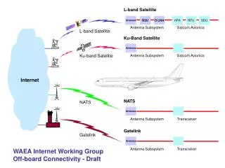
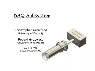
Hardware Architecture • Two major components • Camera transceiver unit • Computer with vision software • Connected via 1.9Ghz RF channel
Software Tools • OpenCV • JavaCV • Netbeans 7.0.1 Integrated Development Environment (IDE)
OpenCV with JavaCV • OpenCV: open source computer vision software library built by Intel Corporation • Image Processing • Object Recognition • Machine Learning • 3D Reconstruction • JavaCV: a wrapper for OpenCV • Allows us to use OpenCV in Java environment • Includes added functionality
Netbeans 7.0.1 • Free, open source IDE • Supports multiple languages including Java • Includes many developer helper functions • GUI & Form Builder • Software Debugger • Unit Testing • Code completion • Integrated subversion (SVN)
Object Discovery • Goal: Find a prominent object in view • Why: Need to initialize object tracking and learning • How: Use the “Snake” algorithm • Based on active contour detection • “Constricts” around strong contours
Object Tracking • Goal: Provide short-term tracking capability in the learning phase is the same object • Why: Assist long-term (learning) tracker • How: • Lucas-Kanade optical flow algorithm • Uses scattered points on object to track motion • CamShift algorithm • Reduces picture color and calculates color histograms
Object Recognition • Goal: Establish a model for an object during the learning phase • Why: • Recover from object occlusion • Provide a basis for egomotion (camera motion) • How: • SURF algorithm • Haar-Like features • Machine learning
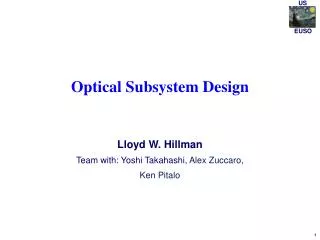
3D Reconstruction • Goal: Establish no-fly zones for the current environment • Why: • Collision avoidance • Path planning • Data visualization • How: Egomotion recovery with stereo vision techniques
Path Planning • Goal: Provide navigational output to user • Why: Builds framework for autonomous navigation • How: • Modified navigation algorithms
Graphical User Interface (GUI) • Goal: Provide data visualization and user input capability • Why: • Destination selection • Navigational output • Internal troubleshooting • How: • Netbeans GUI builder
Camera Calibration & Test Rig • Applications • Camera calibration • Verification of egomotion estimation
Completed Tasks • Integrated JavaCV & OpenCV with Netbeans 7.0.1 IDE • Interfaced with a variety of cameras • Camera calibration & test rig built
Future Work • Module integration • Object recognition • Object tracking • Machine learning • 3D Reconstruction • Obtain depth perception • Egomotion & Stereo techniques • Destination selection • Path Planning • Improved Graphical User Interface (GUI)
Hybrid-mode autonomous navigation for MAV platforms Adrian P. Lauf, P. George Huang Wright State University Center for Micro Aerial Vehicle Studies (CMAVS) Guidance and Control Local Control Loops • Unlike traditional UAVs, MAVs have limited power and computational resources • Qualify as deeply-embedded systems • Weight restrictions are primary obstacle for onboard processing systems • In some cases, aircraft weigh less than 7 grams • The need for autonomy requires the integration of on-board and off-board processing and guidance capabilities • This hybrid schema permits computationally-intensive operations to run without weight restrictions • Various sensor inputs can be used to aid local and global navigation objectives • Video camera images • MEMS gyroscopes • Other heterogeneous mounted sensors • MEMS-based gyroscopes onboard GINA provide information about the aircraft’s stability • Simple PID control can be used to keep aircraft level and stable • Filtering functions can mitigate hysteresis caused by wing motion and control surface actuators • Onboard microprocessor is capable of handling these high-rate, low-complexity tasks • Feedback from PID control can be sent off-board for processing via 802.15.4 radios • Actuator control can be directly handled by the microprocessor; inputs to the system from external sources do not directly actuate control surfaces An airframe and drivetrain example of a CMAVS flapping-wing aircraft Existing receivers and actuators Off-board Control On-board Hardware • Off-line image analysis permits identification of navigation objectives and obstacles • Frame-to-frame analysis allows the system to construct a model of its environment and surroundings • Information contained in the world-model can be used to make navigation decisions • Multiple-aircraft implementations can more quickly and accurately build world-model • Permits joint and distributed operation in an unknown scenario • Allows distributed agents to augment the accuracy of existing models • Commands issued as a result of image analysis can be used as inputs into the PID control navigation routines onboard the aircraft • Each MAV (Micro Aerial Vehicle) equipped with on-board computing module • Guidance and Intertial Navigation Assistant (GINA) • Based on schematics developed at UC Berkeley’s WarpWing project • Modified to reduce weight, unneeded components • Onboard processing allows for vehicle stability in flight • Integrated IEEE 802.15.4 radio protocol permits two-way radio communications • Radio telemetry • External commands • Video image capture and transmission • Without modification, GINA 2.1 weighs over 2.2 grams. • Development will target a weight of 1.5 grams or less Gyroscope output from a GINA module A base-station mote used for the off-board computer