Download
1 / 17
170 likes | 379 Views
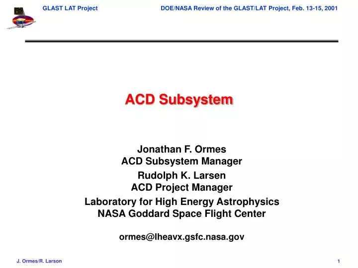
ACD Subsystem. Jonathan F. Ormes ACD Subsystem Manager Rudolph K. Larsen ACD Project Manager Laboratory for High Energy Astrophysics NASA Goddard Space Flight Center ormes@lheavx.gsfc.nasa.gov. Anti-Coincidence (ACD) Subsystem. Outline. Technical overview Requirements Status

E N D
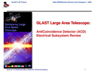
ACD Subsystem Jonathan F. Ormes ACD Subsystem Manager Rudolph K. Larsen ACD Project Manager Laboratory for High Energy Astrophysics NASA Goddard Space Flight Center ormes@lheavx.gsfc.nasa.gov
Anti-Coincidence (ACD) Subsystem Outline • Technical overview • Requirements • Status • Organization • Schedule • Budget • Technical issues and mitigations • Summary
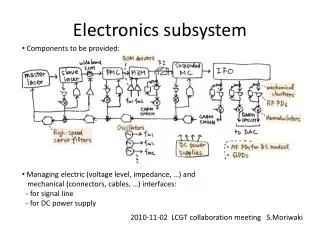
Large Area Telescope (LAT) Design Overview Instrument 16 towers modularity height/width = 0.4 large field-of-view Si-strip detectors: 228 mm pitch, total of 8.8 x 10⁵ ch. hodoscopic CsI crystal array cosmic-ray rejection shower leakage correction XTkr + Cal = 10 X0 shower max contained < 100 GeV segmented plastic scintillator minimize self-veto > 0.9997 efficiency & redundant readout Tracker Calorimeter Anticoincidence Detector Shield 3000 kg, 650 W (allocation) 1.75 m 1.75 m 1.0 m 20 MeV – 300 GeV
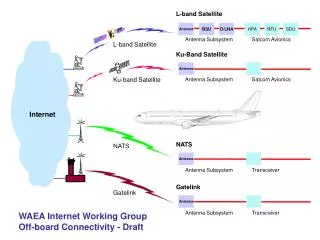
ACD: The First Line of Defense Against Background • The purpose of the ACD is to detect incident cosmic ray charged particles that outnumber cosmic gamma rays by more than 5 orders of magnitude. Signals from the ACD can be used as a trigger veto or can be used later in the data analysis. • Segmented plastic scintillator (Bicron-408) read with wave-shifting fibers (BCF- 91MC) + PMT (Hamamatsu R1635, R4868) readout. • Each segment (tile) has a separate light tight housing. • Separate tile housings provide resistance to accidental puncture by micrometeoroids. • Wave-shifting fiber readout provides light collection uniformity • Gaps between tiles are deliberately misaligned with the gaps between tracker towers and covered by scintillating fiber "tapes"
Design Heritage Backsplash reduced the EGRET effective area by 50% at 10 GeV compared to 1 GeV. GLAST will be studying photons to above 300 GeV. Anticoincidence Detector for GLAST is subdivided into smaller tiles to avoid the efficiency degradation at high energy. 0.2-2 MeV "backsplash" photons GLAST EGRET
Design Approach Lip to "hide" thermal blanket and micro-meteorite shield Segmentation for side entry events
SRD Background Rejection requirement: Contamination of the high latitude diffuse gamma rays by background in any decade of energy for > 100 MeV shall be less than 10%. The goal shall be 1%. Charged particle background rejection involves the use of pattern recognition in the tracker and the calorimeter as well as the ACD. For protons, calorimeter and tracker are powerful. 105 : 1 at system level Electrons are more problematic. Electrons create showers in the calorimeter identical with photon showers. Worst case is 3 x 10³ : 1 at 10 GeV The required ACD efficiency for charged particles (detector efficiency + hermeticity) is 0.9997 Science Requirement: Efficiency
Additional Requirements • Tile segmentation • Efficiency > 80% at 300 GeV relative to that at 1 GeV • Effective area at >60o; >0.1 of on-axis value • No more than 10% loss of effective area • 6% in the plastic and structure • 1% from ACD deadtime • 1% loss from noise • <5% chance of loss of tile in 5 years (electronics) • <1% per year for loss of tile by micrometeoroid puncture
Physical interface specifications • Mass 200 kg + 60 kg (30% reserve) = 260 kg • Electronics 34 kg + 17 kg (50% reserve) = 50 kg • Power 30 watts + 25 watts (80% reserve) • Volume - see materials presented by Martin Nordby • Electronic signals • Fast VETO • Pre-primitives for Trigger thresholds • Hi Z trigger for calibration events • Addresses of hit tiles • Pulse heights of hit tiles • Rate date from all tiles • Housekeeping data • Command, command verification, and control
ACD Technical Status • Detectors: • Scintillator tile light output tests have been performed. • Tile overlapping and detector tapes are planned to cover gaps • Electron background rejection analysis cuts being developed • Side tile segmentation is being reevaluated • Trade studies are being performed • tile thickness, segmentation and PMT placement • Electronics: • ASIC development proceeding • First prototype submission was in January • Higher gain Hamamatsu PMTs are being evaluated • Electronic parts have been submitted for acceptance • High voltage power supply specs, SOW and cost estimate created • Procurement for prototype sent to identified vendors • Mechanical: • Tile support structure has been improved over proposal design
ACD Subsystem 4.1.6 Jonathan Ormes - Lead ACD management 4.1.6.1 Rudy Larsen - Manager Cristina Doria-Warner - Financial Resources Dennis Wicks - Scheduling ACD Design and Science support ACD System Engineering Alexander Moiseev,Lead David Thompson, Robert Hartman Tom Riley David Bertsch, Jay Norris ACD Reliability and Quality Assurance 4.1.6.2 Patricia. Huber, Lead ACD Simulations Russell Murray, Quality John Remez, Reliability Peter Jones, Parts Fred Gross, Materials Bo Lewis, Safety Heather Kelly Taro Kotani Alexander Moiseev Micrometeroid Shield / Thermal Blanket 4.1.6.B Insrument ACD Subsystem Integration & Test 4.1.6.8 ACD Detectors 4.1.6.3 ACD Mechanical Components 4.1.6.5 ACD Electronics 4.1.6.4 Reserved 4.1.6.7 Mission Operation & Data Analysis 4.1.6.A ACD Flight Software 4.1.6.6 Mission Integration & Test Support 4.1.6.9 Alexander Moiseev, Lead Dave Sheppard, Lead Thomas Johnson, Lead Lou Fantano, Thermal Lead Robert Hartman Thomas Johnson, Lead Robert Hartman Robert Schaefer, Lead S. Singh, ASIC design John Lindsay, Lead Tom Johnson David Thompson, Lead John Lindsay, Lead Sharon Seipel John Krizmanic Robert Baker Scot Murphy Fabrication William. Daniels Electrical Test Donald Righter Darrin Buck James Odom ACD WBS Organization Chart All ACD team members above are GSFC civil service employees or GSFC contractors
Contributing GSFC Lead Organizations • WBS 4.1.6 ACD Subsystem - Dr. Jonathan Ormes, GSFC Code 600, Space Science Directorate • WBS 4.1.6.1 ACD Management - Rudy Larsen, GSFC Code 700.1, Project Formulation • System Engineering - Tom Riley, GSFC Code 730.4, Instrument Systems Office • Science Support- Dr. Alexander Moiseev, GSFC/USRA Code 661, Gamma Ray and Cosmic Ray Astrophysics Branch • WBS 4.1.6.2 ACD Reliability and Quality Assurance - Patricia Huber, GSFC Code 303, Assurance Management Office • WBS 4.1.6.3 ACD Detectors - Dr. Alexander Moiseev, GSFC/USRA Code 661 • WBS 4.1.6.4 ACD Electronics - Dave Sheppard, GSFC Code 564, Microelectronics and Signal Processing Branch • WBS 4.1.6.5 ACD Mechanical Components - Tom Johnson, GSFC Code 543, Mechanical Engineering Branch • WBS 4.1.6.6 ACD Software - Bob Schaefer, GSFC/HSTX Code 664, Data Management and Programming Office • WBS 4.1.6.8 Instrument Subsystem Integration & Test - John Lindsay, GSFC Code 568, Flight Systems Integration and Test Branch • WBS 4.1.6.9 Mission I&T Support - John Lindsay, GSFC Code 568 • WBS 4.1.6.A Mission Operations & Data Analysis - Dr. Dave Thompson, GSFC Code 661 • WBS 4.1.6.B ACD Micrometeoroid Shield/Thermal Blanket - Tom Johnson, GSFC Code 543 / • Louis Fantano, GSFC Code 545, Thermal Engineering Branch • ------------------------------------------------------------------------------------------------------------------------------------ • USRA- University Space Research Association EITI - Emergent Information Technologies Inc.
ACD Milestones • ACD & Thermal Blanket Requirements Review 03/21/01 • ACD & Thermal Blanket PDR 06/27/01 • LAT Instrument PDR 08/06/01 • ACD & Thermal Blanket CDR 06/26/02 • LAT Instrument CDR 08/05/02 • ACD Engineering Model (EM) Complete 05/15/03 • ACD Flight Subsystem Assembly Complete 10/01/03 • Thermal Blanket / Micrometeoroid Shield Ready for Integration 02/01/03 • (with thermal model) • Delivery of Calibration Unit ACD to SLAC 05/15/03 • Flight ACD Ready for Integration 01/26/04
Interim ACD Cost Estimate* (Escalated K$) *DOE/NASA funding.
Technical Issues and Mitigations • Increase technical margin for light collection • Add reflective termination to fibers or read out at both ends • Monitor and adjust PMT gain in flight • Request 25-30 kg additional mass for thicker tiles on top • Required volume for electronics may exceed available • Place PMTs under ACD • Place some of electronics underneath the grid • Reduce side segmentation • Parts acceptance and procurement • Prototype HVPS procurement is in preparation • Parts list submitted to Quality Assurance Branch • Integration highly coupled to design • ACD I&T manager appointed to work with design team
Summary • ACD team is in place and progress is quite rapid • Necessary trade studies underway • Optimization of side segmentation • Optimization of redundancy • Optimization of light collection; tile thickness • Requirements have been established • Near term schedule advanced • Received additional funding for FY '01 • Added staff to prepare for PDR • Draft Level 6 schedule is in hand • Grass roots costing being scrubbed