Download
1 / 50
620 likes | 985 Views
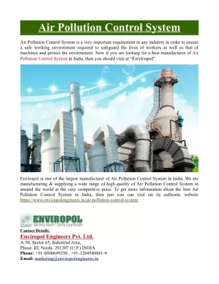
Air Pollution Control Technologies. VOC Incinerators. VOCs. Includes pure hydrocarbons and partially oxidized compounds (organic acids, aldehydes, ketones) There are hunderds of individual compounds with each with its own properties and chracteristics

E N D
Air Pollution Control Technologies VOC Incinerators
VOCs • Includes pure hydrocarbons and partially oxidized compounds (organic acids, aldehydes, ketones) • There are hunderds of individual compounds with each with its own properties and chracteristics • Combustion processes, various industrial operations and solvent evaporation are the main sources
VOC Incineration • Vapor incinerators are also called thermal oxidizers and afterburners • They can be also used successfully for air polluted with small particles of solids or liquids. • Incineration can be used for odor control, to destroy a toxic compound, or to reduce the quantity of photochemically reactive VOCs released to the atmosphere
VOC Incineration • VOC vapors might be in a concentrated stream (such as emergency relief gases in a petroleum refinery) or might be a dilute mixture in air ( such as from a paint-drying oven) • In the case of a dilute fume in air two methods are used • Direct thermal incineration • Catalytic oxidation
VOC Incineration • In some sources (such as printing presses or parts-painting stations), emissions need to be captured by hoods and a common duct system and routed to a thermal oxidizer (TO) • Total VOC reduction in this case depends on both the destruction efficiency of TO and capture efficiency • Total efficiency will be equal to destruction efficiency times capture efficiency
VOC Incineration • The main disadvantage of the VOC incineration is the high fuel cost • Some of the products of combustion of some VOCs are themselves pollutants • When a chlorinated HC is burned HCl and Cl2 will be emitted and then additional control for these pollutants might become neccessary
Alternatives to VOC Incineration • Biofilter • Wet scrubber • Recovery of the vapors (recompression, condensation, carbon adsroption or liquid absorption) If very stringent control objective exists, only incineration can achieve that e.g. Reduction in concentration from 10,000 ppm to 5 ppm for some malodorous organic sulfur compounds.
Oxidation Chemistry • Consider only the case of a premixed dilute stream of a pure HC in air • CxHy + (b)O2+3.76(b)N2xCO2+(y/2)H2O+3.76(b)N2 CxHy the general formula for any HC b= x+(y/4) 3.76=the number of moles of N2 present in air for every mole of O2
Oxidation Chemistry • (b)O2+3.76(b)N2xCO2+(y/2)H2O+3.76(b)N2 The actual detailed mechanisms of combustion are complex and do not occur in a single step as might be inferred from above eqn. The mechanism involves a branching chain reaction and further complicated by the larger number of possible intermediates for higher order HCs.
Oxidation Chemistry • (b)O2+3.76(b)N2xCO2+(y/2)H2O+3.76(b)N2 The actual detailed mechanisms of combustion are complex and do not occur in a single step as might be inferred from above eqn. The mechanism involves a branching chain reaction and further complicated by the larger number of possible intermediates for higher order HCs.
Major Reactions in CH4 Oxidation Chain initation CH4 +O2CH3·+HO2 CH3·+O2CH2O·+OH CH4+OHCH3 ·+ H2O CH2O+OHHCO ·+ H2O CH2+O2HO2 ·+ HCO · HCO+O2CO+HO2 · HO2+CH4H2O2+CH3 · HO2+CH2OH2O2+HCO · OH · wall CH2O · wall Chain propagation Chain branching Chain propagation Chain termination
Developing Global Models • Instead, global models ignores many of the detailed steps and ties the kinetics to the main stable reactants and products • Since CO is a very stable intermediate, the simplest two step model for HC oxidation is: CxHy+(x/2+y/4)O2xCO+(y/2)H2O 11.2 xCO+(x/2)O2xCO2 11.3
Global Model Kinetics • Using Eqs 11.2 and 11.3 a global kinetic model that is of the first order in each reactant results in the rate equations: rHC=-k1[HC][ O2] rCO=xk1[HC][ O2] – k2[CO][ O2] and in the presence of excess O2: rHC=-k1[HC] rCO=xk1[HC]– k2[CO] A third equation for CO2: rCO2=-k2[CO]
Global Model Kinetics • Those 3 equations represent a special case of a general set of consecutive first order irreversible reactions: ARS Levenspiel (1962) presented solutions for the concentration of all components as a function of dimensionless reaction time for various k2/k1 ratios. k1 k2
The Three T’s • Temperature • Time • Turbulence For good destruction afterburners should be designed for temperatures 650-1100 C, for residence times of 0.2-2 sec, and for flow velocities of 20-40 ft/sec Afterburner is now a standart as part of a hazardous waste incinerators requiring %99.99 destruction and removal efficiency of the Principal Organic Hazardous constituents
The Three T’s • In mathematical sense 3Ts are related to 3 characteristic times: tC=1/k Chemical time tr=V/Q=L/u Residence time tm=L2/De Mixing time V: Volume of the reaction zone, m3 Q: Flow rate (at T in the afterburner) , m3/s L: Length of the reaction zone, m u: gas velocity, m/s De: effective (turbulent) diffusion coef. m2/s
The Three T’s Peclet number: Pe= Mixing time/residence time Damkohler number: Da=Residence time/chemical time If Pe is large and Da is smallmixing is the rate controlling process in the afterburner If Pe is small and Da is largechemical kinetics is the rate controlling process
Predicting VOC Kinetics • Kinetics are surely important to the proper desing of an afterburner but kinetic data are scarce and difficult and costly to obtain by pilot studies • So past methods of determining the desing or operating temperature of an incinerator were very rough at best
Predicting VOC Kinetics1. Ross’s Approach • Ross (1997) summarized the older methods by suggesting Tdesign be set several hunders degrees (F) above the VOC autoignition temperature Autoignition T: the temperature at which cobmustible mixtures of the VOC in air will ignite without an external source • Excessively high design Ts will result in very high estimated costs for purchasing and operating a VOC incinerator
2. Lee and coworkers’ Approach • A purely statistical model to predict the Ts required to give various levels of destruction in an isothermal plug flow afterburner based on their experimental studies • T99.9= 594-12.2W1+117W2+71.6W3+80.2W4+0.592W5-20.2W6-420.3W7+87.1W8-66.8W9+62.8W10-75.3W11 • T99= 577-10W1+110.2W2+67.1W3+72.6W4+0.586W5-23.4W6-430.9W7+85.2W8-82.2W9+65.5W10-76.1W11 • T99.9= T for 99.9% destruction efficiency, F • W1=number of carbon atoms • W2= aromatic carbon flag (0=no,1=yes) • W3= C C double bond flag (0=no,1=yes) • W4= number of N atoms • W5= autoignition Temperature, F • W6= number of O atoms • W7= number of S atoms • W8= hydroge/carbon ratio • W9= allyl (2-propenyl) compound flag (0=no,1=yes) • W10= carbon-double-bond-chlorine interaction (0=no,1=yes) • W11= natural log of residence time
Predicting VOC Kinetics3. Cooper, Alley and Overcamp’s Approach Combined collision theory with empirical data and proposed a method to predict an effective first order rate constant k for HC incineration over the range from 940 to 1140 K. The method depends on MW and the type of the HC Once k is found, Tdesign can be obtained A: pre-exponential factor Z’: collision rate factor (from Figure 11.5 for alkanes, alkenes, and aromatics) S=steric factor: to account for the fact that some collisions are not effective in producing reactions becasue of molecular geometry S=16/MW yO2: mole fraction of O2 in the afterburner P: absolute pressure, atm R’: gas constant, 0.08206 L-atm/mol-K
Predicting VOC Kinetics3. Cooper, Alley and Overcamp’s Approach The activation energy E=-0.00966(MW)+46.1 (From figure 11.6) Now k can be calculated for any desired temperature. In an isothermal pluf flow reactor (PFR) the HC destruction efficiency, the rate constant and the residence time are related as:
Predicting Overall Kinetics The destruction of VOC occur quickly relative to CO destruction The kinetics of CO destruction have been studied by many researchers Howard published the following expression for CO oxidation (valid for the range of 840-2360 K) Destruction rate of CO = 1.3(10)14e-30,000/RT{O2}1/2 {H2O}1/2{CO} Where { }indicates concentration in mol/cm3 This equation can be combined with the VOC kinetic.
Example 11.1 • Estimate the temperature required in an isothermal plug flow incinerator with a residence time of 0.5 sec to give 99.5% destruction of toluene by using 3 methods given. Method 1. autoignition T + 300 F=1026+300 = 1326 F
Example 11.1 • Method 2. Lee et al. • T99.9= 594-12.2(7)+117+0+0+0.592(1026)-0-0+87.1(11.4)-0+0-75.3ln(0.5) • T99= 577-107+110.2+0+0+0.586(1026)-0-0+85.2(1.14)-0+0-76.1ln(0.5) T99.5 can be calculated by taking a linear average: T99.5=(T99.9+T99)/2=1378 F
Example 11.1 • Method 3. Cooper et al. First calculate required value k E=-0.00966(MW)+46.1 S=16/MW=16/92=0.174 Z’=2.85(10)11 Then calculate A Now find T
Catalytic Oxidation • Catalyst: is an element or a compound that speeds up a reaction without undergoing permananet change itself • Gaseous molecules diffuse to and adsorb onto the surface of the catalyst • After reaction product gases desorb and diffuse back into the bulk gas stream • The detailed mechanisms of the reaction are not known but the reaction proceeds much faster and/or at much lower T
Design Considerations for Thermal Oxidizers • The process of a VOC thermal oxidizer involves selection of • Operation T • Residence time • Sizing the device to achieve those with the proper flow velocity Factors: O2 content Type of operation (continous or intermittent) Concentration of VOCs
Design Considerations for Thermal Oxidizers • To minimize the cost, it is desirable to keep the stream to be treated as low as possible • i.e. Not dilute VOC streams with too much air • However most insurance regulations limit the max VOC concentraiton to 25% of the lower explosive limit (LEL) of the VOC
Design Considerations for Thermal Oxidizers • Materialandenergybalancesareperformedtothe device tocalculatetheflow rate of fuelgasrequiredtoraisetheair T at a givenflow rate totherequired T. • 2 Methods • Thetraditionalapproach: assume an isothermalplugflowreactor • Theuse of computer program tohandlethecalculationsandallowsfornon-isothermaloperation
Method 1. Traditional Approach • Material and energy balance: Polluted air (PA) Burner air (BA) Fuel Gas (G) Exhaust gas (E) Mass flow rates (kg/min) Burner Net heat of combustion Lower heating value kj/kg Flame mixing chamber Reactionchamber Material Balance Energy Balance h: Specific enthalpy kj/kg Xi:Fractional conversion of VOCi
Method 1. Traditional Approach • If we assume that enthalpy functions of all streams similar to those for pure air and consider all heat losses (qL)as a simple fraction of the heat input (fL):
Method 1. Traditional Approach Fuel gas is mixed with the outside ambient air in a preset ratio Rb, then MBA=RBMG, also T of burner air equals to T of fuel gas then the equation takes its final form:
Example 11.2 • Calculate the mass flow rate of CH4 required for an afterburner to treat 2645 acfm of polluted air. It is estimated that the burner will bring in 200 scfm of ouside air. The fuel gas enters at 80 F and the burner air enters at 80 F. The lower heating value (LHV) of CH4 is 21560 Btu/lb. Assume 10% overall heat loss and ignore any heat gained by the oxidation of the pollutants. • SOLUTION From Appendix Table B.2, densities of the inlet PA and BA are 0.060 and 0.074 lb/ft3. MPA = 2465 acfm (0.060 lb/acf)=148 lb/min MBA = 200 scfm (0.074 lb/acf)=14.8 lb/min Appendix Table B.7 enthalpies: hTE= 328 hTBA= 4.8 hTBA= 33.6 hTG= 4.8
Example 11.2 SOLUTION MPA = 2465 acfm (0.060 lb/acf)=148 lb/min MBA = 200 scfm (0.074 lb/acf)=14.8 lb/min hTE= 328 hTBA= 4.8 hTBA= 33.6 hTG= 4.8 Btu/lb fL:0.1 MG = 2.53 lb/min
Sizing the Device • To ensure adequate mixing and to approach the condition of plug flow a linear velocity of 20-40 ft/sec recommended • Usually the residence time 0.4-0.9 sec is enough • For hazardous waste incinerator residence time must be 2 sec or longer • For biomedical waste incinerator residence time must be 1 sec or longer
Sizing the Device • Length of the reaction chamber (L) is given by • L=utr • The volumetric flow rate (Q)from the ideal gas law: • The diameter of the chamber (D)
Example 11.3 • Specify the length and the diameter of the afterburner of Example 11.2 given that the design velocity in the main chamber is 15 ft/sec and the desired residence time is 1 sec
Solution • Length of the reaction chamber L=utr=15(1.0) = 15 ft ME=148+14.8+2.5=165 lb/min • The volumetric flow rate (Q)from the ideal gas law: • The diameter of the chamber (D)
General Approach • Start with equation 11.21 and 22 for a small slice of the afterburner • Treat each small slice as a CSTR • The fraction combusted depends on T, k and residence time in the CSTR • Assume an inlet T and kinetic model of 11.6 and 11.7 for both VOC and CO • Because of the heat losses and gains Texit and Tinlet are different • Use iterative appraoch to find outlet T and CO and VOC concentrations • Repeat the procedure for all small CSTRs • If the outlet VOC and CO concentrations are not those desired, start with a new assumed inlet T.
Design Considerations forCatalytic Oxidizers • Can reduce the required temperatures by hunders of degrees and can save considerable amount of space for equipment as compared with thermal oxidizers • Catalysis is usually a noble metal such as palladium or platinum deposited on an alumina support in a configuration to give miniumum pressure drop • The pressure drop consideration is often cirtical for incinerator design
Design Considerations forCatalytic Oxidizers • A honeycomb arrangement typically results in a pressure drop of 0.05-0.5” H2O/inch of bed depth • Packed bed of 1/8” diameter pellets 1.0-10” H2O/inch of bed depth
Design Considerations forCatalytic Oxidizers • Catalyst activity refers to the degree to which a chemical reaction rate is increased compared with the same reaction without the catalyst. They can also be very selective. Such activity and selectivity translated into lower operating temperatuerd required for the desired percentage of destruction.
Design Considerations forCatalytic Oxidizers • Table 11.4 Some T used for catalytic incineration
Basic Design Equation [VOC]L/[VOC]0=e-L/Lm [VOC]L :concentration of the VOC at length L [VOC]0= inlet concentration of the VOC L=length of catalyst bed Lm=length of one mass transfer unit If Re<1000 Then Lm=ud2/17.6D u: linear velocity in the channel d=effective diameter of the channel D=diffusivity, m2/s
Basic Design Equation [VOC]L/[VOC]0=e-L/Lm [VOC]L :concentration of the VOC at length L [VOC]0= inlet concentration of the VOC L=length of catalyst bed Lm=length of one mass transfer unit If Re<1000 Then Lm=ud2/17.6D u: linear velocity in the channel d=effective diameter of the channel D=diffusivity, m2/s
Basic Design Equation If the flow is turbulent then Lm=2/fa(Sc)2/3 f: Fanning friction factor a=surface area per unit voluem of bed, m-1 Sc=Schmidt number (m/pD) The calculated length (usually 2-10” for 99% removal)should be doubled for the safety of the design Catalyst surface area 0.2-0.5 ft2 per waste gas