Download
1 / 48
500 likes | 902 Views
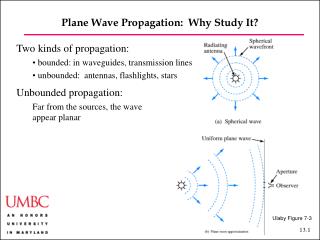
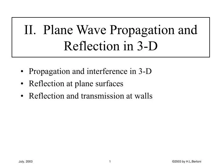
II. Plane Wave Propagation and Reflection in 3-D. Propagation and interference in 3-D Reflection at plane surfaces Reflection and transmission at walls. Propagation and Interference in 3-D. Physical properties of plane waves Mathematical expressions for the spatial variation

E N D
II. Plane Wave Propagation and Reflection in 3-D • Propagation and interference in 3-D • Reflection at plane surfaces • Reflection and transmission at walls ©2003 by H.L.Bertoni
Propagation and Interference in 3-D • Physical properties of plane waves • Mathematical expressions for the spatial variation • Interference of waves for propagation in a plane • Rayleigh and Rician statistics • Spatial correlation of the fields and Doppler Spread ©2003 by H.L.Bertoni
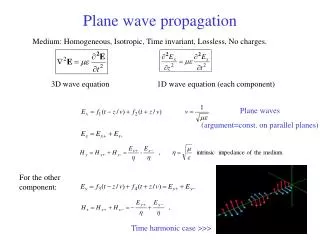
Maxwell’s Equations for Harmonic Time Dependence • Plane waves are solutions of Maxwell’s equations ©2003 by H.L.Bertoni
z y x Plane Waves in 3-D ©2003 by H.L.Bertoni
z y x Expressions for the Fields ©2003 by H.L.Bertoni
y Plane of constant phase q x z Plane Waves Propagating in the x-y Plane ©2003 by H.L.Bertoni
Interference of Multiple Plane Waves ©2003 by H.L.Bertoni
20 10 0 V1=1 -10 V1=4 V1=8 -10 -5 0 10 15 Amplitudes: V1= 1 V1= 4 V1= 8 V2= = V8= 1 V2= = V8= 1 V2= = V8= 1 Phases chosen randomly 0 ~ 2 Fast Fading of Field for Eight Plane WavesThe Propagation AnglesqnAreRandomly Chosen |Ez| (dB) x/l ©2003 by H.L.Bertoni
Statistics of the Fast Fading ©2003 by H.L.Bertoni
p (r) r Rayleigh and Rician PDF’s ©2003 by H.L.Bertoni
1.0 Median value = 0.939 0.8 0.6 CDF 0.4 Rayleigh CDF Rician CDF 0.2 K=5 0 0 0.5 1.0 1.5 2.0 2.5 r Rayleigh and Rician CDF’s ©2003 by H.L.Bertoni
1 V1=4 CDF 0.5 V1=8 RayleighDistribution V1=1 0 0 0.5 1 1.5 2 2.5 CDF of Simulated Field Amplitude ©2003 by H.L.Bertoni
Complex Autocorrelation Function ©2003 by H.L.Bertoni
Auto-Correlation Function for Plane Waves ©2003 by H.L.Bertoni
1.0 0.8 0.6 0.4 J0(ks) 0.2 0 2 4 6 8 10 ks -0.2 -0.4 Correlation Distance for Mobiles ©2003 by H.L.Bertoni
Sample Number d (m) 4 0.26 1 2 C(s) Measured Street Level Measurements made at f = 821 MHz l= 0.365 m Signal de-correlated afterd >l /4 S-B. Rhee and G.I. ZYsman, "Results of Suburban Base Station Spatial Diversity Measurements in the UHF Band," IEEE Trans. on Comm., vol. COM-22, pp. 1630-1636, 1974. ©2003 by H.L.Bertoni
wave direction q subscriber velocity u Doppler Spread for Moving Subscribers ©2003 by H.L.Bertoni
Measured Doppler Spread(1,800 MHz) K.I. Pedersen, et al., "Analysis of Time, Azimuth and Doppler Dispersion in Outdoor Radio Channels,” Proc. ACTS, 1997. ©2003 by H.L.Bertoni
Local Scatterers a x s Correlation for Limited Range of Angles ©2003 by H.L.Bertoni
Auto-Correlation for Real Signals ©2003 by H.L.Bertoni
CR(s) Measured at 900 MHz in Liverpool, England Real Correlation at Elevated Base Station F. Adachi, et al., "Cross correlation between the envelopes of 900 MHz signals received at a mobile radio base station site," IEE Proc., vol. 133, Pt. F, pp. 506-512, 1980. ©2003 by H.L.Bertoni
Summary of Propagation and Interference • Plane waves have phase fronts that are perpendicular to the wave vector k • E, H, k form a right hand system and |E| = |H| • Interference of multiple plane waves produces an irregular standing wave pattern in space • For equal amplitude plane waves arriving from all directions the distribution of total field strength is nearly Rayleigh distributed • Field strength is Rician distributed for plane waves of un-equal amplitude • Correlation distance of standing wave pattern depends on the angular range of arrivals • Doppler spread is found from the correlation function. ©2003 by H.L.Bertoni
Reflection of Plane Waves at a Dielectric Surface Snell’s Law Reflection for TE and TM Polarization Height gain for reflection from ground
q q q x q qT qT Snell's Law for Oblique Incidence y Graphical interpretation of Snell’s law ©2003 by H.L.Bertoni
y Ez + - q q Hx x z qT Transmission Line Representation for Transverse Electric (TE) Polarization ©2003 by H.L.Bertoni
y Ex + - q q Hz x z qT Transmission Line Representation for Transverse Magnetic (TM) Polarization ©2003 by H.L.Bertoni
GE 90º q -1 GH 90º qB q -1 Reflection from a Dielectric Half-Space • TE Polarization • TM Polarization ©2003 by H.L.Bertoni
1 1 0.9 0.9 er=81 er=81 0.8 0.8 Reflection coefficient |GH| Reflection coefficient |GE| er=25 0.7 0.7 er=25 er=16 er=16 0.6 0.6 er=9 er=9 0.5 0.5 0.4 0.4 er=4 er=4 0.3 0.3 er=2.56 er=2.56 0.2 0.2 0.1 0.1 Incident AngleqI Incident AngleqI 0 0 0 15 30 45 60 75 90 0 15 30 45 60 75 90 TE Polarization TM Polarization Magnitude of Reflection Coefficients at a Dielectric Half-Space ©2003 by H.L.Bertoni
y y x q ym |Ez| x Height Gain for Reflection From Flat Earth ©2003 by H.L.Bertoni
Summary of Plane Wave Reflection • Continuity of fields at an interface requires that the components of the wave vectors parallel to the interface all be equal • Impedances for TE and TM polarizations allows the use of transmission line formulas for reflection and transmission coefficients • TM wave experience total transmission at Brewster’s angle • Interference of the incident and ground reflected waves results in height gain for an antenna ©2003 by H.L.Bertoni
Reflection and Transmission at Walls Transmission line formulation Homogeneous walls Attenuation in walls Inhomogeneous walls
ZaTE ZdTE w ZaTE ZaTE ZdTE ZaTE Transmission Line Formulation for a Wall ©2003 by H.L.Bertoni
Incident Za Zw Za Transmitted Reflected ZL=Za Z(w) Standing Wave - w 0 Transmission Line Method air wall air ©2003 by H.L.Bertoni
1 0.8 900MHz 20cm TE 0.6 G 2 1.8GHz TE 0.4 900MHz TM 0.2 1.8GHz TM 0 0 10 20 30 40 50 60 70 80 90 Angle of Incidence qI (degree) B Reflection at Masonry Walls(Dry Brick:er 5, e”=0) ZaTE ZdTE ZaTE ©2003 by H.L.Bertoni
Za Z(w) Zw,kw z - w 0 Reflection Accounting for Wall Loss ©2003 by H.L.Bertoni
1 1 Measured data Measured data 0.9 0.9 w = 0.8 0.8 0.7 0.7 w = 30cm 0.6 0.6 G G w = 0.5 0.5 0.4 0.4 0.3 0.3 w = 30cm 0.2 0.2 0.1 0.1 0 0 0 15 30 45 60 75 90 0 15 30 45 60 75 90 Angle of Incidence q Angle of Incidence q TE Polarization TM Polarization Comparison with Measured |G|4 GHz forReew = 4,Imew = 0.1 and l = 30 cm(Landron, et al., IEEE Trans. AP, March 1996) ©2003 by H.L.Bertoni
I(0) V(0) + Za Zw,kw z Z(w) 0 w Transmission Loss Through Wall ©2003 by H.L.Bertoni
Transmission Loss Through Wall, cont. ©2003 by H.L.Bertoni
TawTwae-w w Approximation for Transmission Loss ©2003 by H.L.Bertoni
4.5" Dielectric 1" 1" 5/8" Metal Stud 1.5" 16” 2.5" Air Air 1.5" Gypsum board Transmission Through Walls with Internal Structure a ) Gypsum board wall b ) Concrete block wall ©2003 by H.L.Bertoni
Reflection by Gypsum Board Wall: No Studs Double 5/8 in. gypsum board sheets 3.5 in. apart Incident wave has TE polarization For incidence up to 30o the transmission loss ~ 1 - 3 dB ©2003 by H.L.Bertoni
Specular Transmission n = -1 n = 0 p h1 n = +1 e2 e2 e2 h2 e2 n = +1 Incident wave n = 0 h1 n = -1 Specular Reflection kn= k0 sinq+ 2pn/p > 0 Diffraction Orders Are Generated by Periodic Structures ©2003 by H.L.Bertoni
Transmission Computed for Gypsum Board Wall vs. Angle of Incidence at 2.4 GHz ©2003 by H.L.Bertoni
Interior Wall qi qr Rx Tx Arrangement for Measuring Transmission Through Walls Using Horn Antennas ©2003 by H.L.Bertoni
10/8" Metal Stud 2' 6" Air 13/8" Gypsum board Transmission Through Gypsum Board Wall(Normal Incidence, f = 2.6 GHz) Oversized gypsum board wall used for measurements ©2003 by H.L.Bertoni
Transmission Through Concrete Block Wall(Normal Incidence, f = 2.6 GHz) Computed Measured ©2003 by H.L.Bertoni
Wall Loss Measured by Various Means ©2003 by H.L.Bertoni
Summary of Wall Reflection / Transmission • Layered walls can be treated by cascading impedance transformations • Angle and frequency dependence of wall without loss show strong interference effects in G and T • Wall loss (absorption) damps out multiply reflected waves, and reduces interference effects in G and T • Internal structure in walls scatters some of the incident energy in non-specular directions ©2003 by H.L.Bertoni