Download
1 / 32
360 likes | 503 Views
Dive into wave propagation and understand the relationship between frequency, wavelength, and speed of propagation. Learn how to differentiate between reflection, refraction, and diffraction, and solve refraction angles using Snell’s Law. Explore the concepts of constructive and destructive interference, identify EM band designations, and solve for radar horizon. Discover the characteristics of mechanical and electromagnetic waves, along with energy fundamentals and wave terms. Uncover the principles of Fourier Analysis and electromagnetic wave propagation paths. Enhance your knowledge on reflection, refraction, and diffraction along with interference phenomena in electromagnetic waves.

E N D
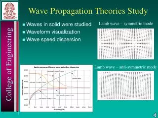
Objectives • Apply the relationship between Frequency, Wavelength and the Speed of Propagation • Distinguish between Reflection, Refraction, and Diffraction • Solve refraction angles using Snell’s Law • Explain the relationship between an electric field and it’s magnetic field and how because of this relationship, electromagnetic waves propagate • Explain Constructive and Destructive Interference and calculate the amount of Interference and Phase Angle • Identify the range of frequencies associated with each EM band designation • List the various wave propagation paths and the band designations associated with the propagation • Solve for the radar horizon using the height relationship between the target and sensor
Particles vs. Waves • Two great concepts in physics • Particles suggest a tiny concentration of matter capable of transmitting energy • Waves suggest just the opposite – a broad distribution of energy filling the space through which it passes.
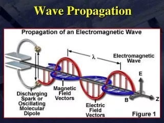
Wave Characteristics • Two Types (for our purposes). • Mechanical~ Requires medium for propagation • Sound (Sonar) (Air or Water) • Electromagnetic ~ Doesn’t require medium for propagation • Light (Air or Water) • Radio (Air or Water) • Radar (Air) • Mechanical Waves Propagate as Longitudinal Waves • Disturbance in line with direction of propagation • Electromagnetic Waves Propagate as Transverse Waves • Disturbance right angles to direction of propagation
Energy Fundamentals • RAdioDetectionAndRanging • Radar is an electromagnetic wavethat acts like any other electromagnetic wave (radio, light, etc.) • Characteristics of a radio wave assuming a frequency of 50 Hertz: 1 Cycle / .02 Sec 50 Cycles / 1 Sec
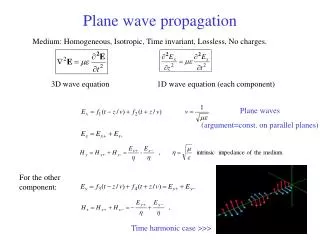
Wave Propagation • Spherical Wave (Near Field) • Undisturbed wave • Omni directional from source • Ripples on a pond. • Plane Wave (Far Field) • Far from origin • Spreads out to appear to have same amplitude everywhere on plane perpendicular to direction of travel • Think of entire wave traveling in one direction
Wave Terms • Frequency (f) – Rate at which source disturbance oscillates through one complete cycle (Hertz – Hz sec –1) • Wavelength (l) – Distance between two identical points on adjacent waves or distance traveled by wave in one cycle. (Length cm, mm, m) λ = c/f • Velocity (c) – EM waves travel at speed of light, (c = 3 x 10⁸ m/s) • Amplitude (A) – Maximum displacement of wave from constant reference value. • Period (T) – Time to complete one cycle (time, sec)
Phase Positive phase shift wave is advancedNegative phase shift wave is retarded • Identical Waves shifted either ahead or behind due to distance separations or time delay. • Pick one as a reference and determine phase difference or phase shift between the two. Phase is measured in either degrees or radians. radians = (2p/360o) x degreesdegrees = (360o/2p) x radians 57.3o per radian
Fourier Analysis • French mathematician Jean Baptist Fourier explained how the principles of interference can be used to analyze non-sinusoidal wave forms. • Specifying amount and frequency of each component (cosine and sine waves) is representative of frequency domain. 8 Hz easily recognizable, other freqs. questionable.
Propagation Paths of Electromagnetic Waves • Reflection • Refraction • Diffraction • Absorption
Reflection • Medium boundaries with dissimilar propagation result in reflection Diffuse reflection results from waves striking an irregular surface and reflecting over a broad range Specular reflection is reflected at equal but opposite angle from smooth surface
Reflection • When we examine at the ‘particle’ level…
Refraction • Incident wave passes through two transparent media in which the velocity of light differs • Incident wave divides into a reflected wave and a refracted wave. • As the angle of incidence increases, angle of refraction increases • When the angle of refraction = 90o then critical angle • For a range of incidence greater than 90o, no refraction, only internal reflection No internal reflection when starting in a lower n because sin 1
Refraction • Electromagnetic waves propagate at speed of light (c) = 3 x 10⁸ m/s (in vacuum) • Speed of light varies in different medium (Cm) • Light refracts at medium boundary layer. • Index of refraction, n, defined as; • n = c/cm We can determine either indices of refraction or angle of refraction by applying Snell’s Law n1sinq1 = n2sinq2
Diffraction • Spreading of wave along edge of an object • Amount of diffraction is wavelength and size related • Wave ‘bends’ when wavelength is larger than object or opening • Can hear around corner, but can’t see around a corner. • Radar can detect around an object under the right conditions
Interference 0o Constructive Constructive 240o 120o Destructive • Interference – when two or more waves collide, superposition of amplitudes add to produce a resulting wave. • Described as either constructive or destructive interference, depending on phase shift between waves. • Constructive – phase difference between 0o and 120o or between 240o and 360o . • Destructive – phase difference between 120o and 240o .
Electromagnetic Signal Loss • Spreading - energy distributed over an increasingly larger area. Energy per unit area proportional to 1/R2. • Absorption - energy dissipated into medium. Molecules of medium absorb some of the energy as it passes through. • Scattering - energy bouncing off suspended particles within a medium. Scattering is going to be particulate size/radar frequency dependent.
Wave Propagation • There is a relationship between distance and frequency • Propagation Modes • Ground Wave • Sky Wave • Space Wave
Ground Wave • Very low frequencies (5-10Khz) • Vertical polarization • Waves travel along earth’s surface. • Very long wavelengths - unsuitable for ships & aircraft, but used for sub comms • Shore-based installations (HF-DF)
Sky Wave • E-M energy refracts in upper ionosphere and is directed back to Earth. May occur multiple times • Frequencies used up to 550 KHz effectively • Wavelengths still too long for anything but comms by aircraft and ships. (Antenna Length)
Space Wave • Higher frequency signals that penetrate the ionosphere and travel through space. • Above 30 MHz, ionosphere will not refract E-M waves back toward earth. • Energy tends to travel in straight line.
Atmospheric effects on Space Waves • Ionospheric Scatter • Scattered reflection of VHF and up signals • 600 – 1000 miles • Tropospheric Scatter • Scattering signal off of troposphere. • Air turbulence, irregularities in refractive index, homogeneous discontinuities. • Boundary layers between stratified pockets of air. • Strong function of weather. • 400 miles. • Tropospheric ducting • Present in inversion conditions (as is all ducting). • Refraction curve matches curvature of the earth. • Improves ranges greatly.
Radar Line of Sight • Due to refraction, certain electromagnetic waves can transmit farther than the “visual” Line of Sight (LOS).
Radar Horizon (LOS) • To compute the maximum detection range between a target and electromagnetic transmitting antenna, the following equation can be employed: • HT = Target Height in METERS • HR = Radar Antenna Height in METERS • Resultant Range is in Kilometers!
Objectives • Apply the relationship between Frequency, Wavelength and the Speed of Wave Propagation • Distinguish between Reflection, Refraction, and Diffraction • Solve refraction angles using Snell’s Law • Explain the relationship between an electric field and it’s magnetic field and how because of this relationship, electromagnetic waves propagate • Explain Constructive or Destructive EM wave Interference waves and calculate the amount of Interference and Phase Angle • Identify the range of frequencies associated with each EM band designation • List the various wave propagation paths and the band designations associated with the propagation • Solve for the radar horizon using the height relationship between the target and sensor