Download
1 / 14
140 likes | 307 Views
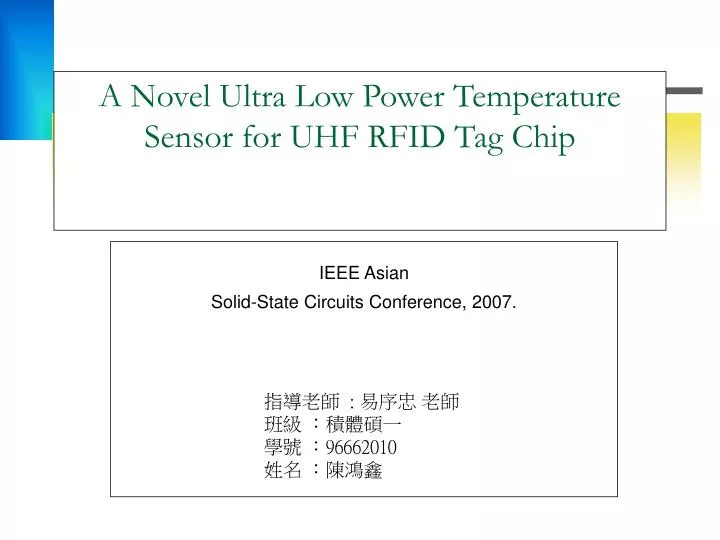
A Novel Ultra Low Power Temperature Sensor for UHF RFID Tag Chip. IEEE Asian Solid-State Circuits Conference, 2007. 指導老師 : 易序忠 老師 班級 :積體碩一 學號 : 96662010 姓名 :陳鴻鑫. Outline. INTRODUCTION ARCHITECTURE CIRCUIT

E N D
A Novel Ultra Low Power Temperature Sensor for UHF RFID Tag Chip IEEE Asian Solid-State Circuits Conference, 2007. 指導老師 : 易序忠 老師 班級 :積體碩一 學號 :96662010 姓名 :陳鴻鑫
Outline • INTRODUCTION • ARCHITECTURE • CIRCUIT A. Constant Pulse Generator B. Comparator C. Oscillator D. Calibration • ACCURACY DISCUSSION • IMPLEMENTATION AND TEST • CONCLUSION
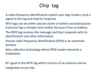
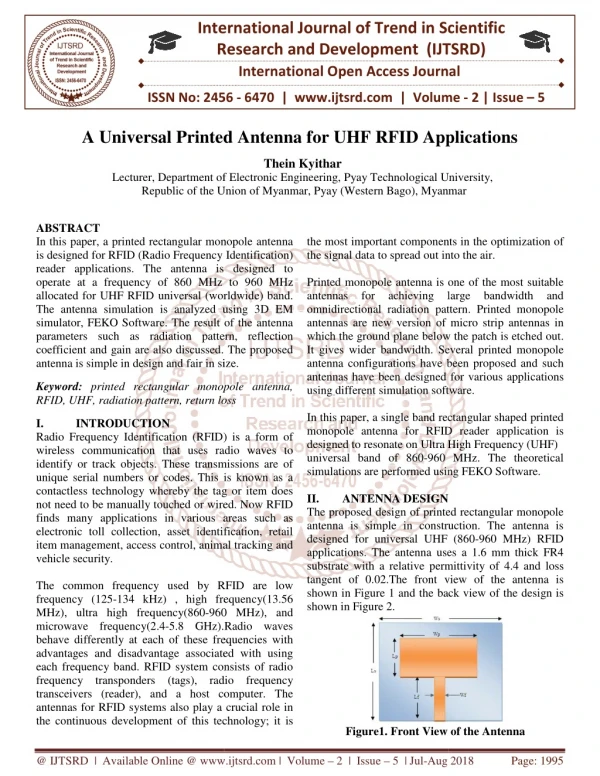
INTRODUCTION • The passive UHF RFID is widely applied in supply chain management. Passive UHF RFID tags have the advantages of longer operating distance and lower cost than low frequency RFID tags. • The RFID tag with embedded sensors will play an important role in the supply chain management and wireless sensor network (WSN). However, the passive RFID tag chip is so sensitive to power consumption that it is difficult to embed sensors and ADC in normal way without shortening the UHF RFID tags’operating range • This paper presents a novel temperature sensor that adopts time domain comparing to avoid the bandgap voltage references and traditional ADCs with larger power consumption to achieve ultra low power.
ARCHITECTURE • The constant pulse generator produces pulses. The temperature coefficient of the pulse frequency is small. • The counter uses the clock of the temperature related oscillator as the counting clock and uses the pulse of the constant puls generator as the reset signal. • The calibration circuits are designed in the bias, the constant pulse generator and the counter to compensate the effect of fabrication process fluctuation.
CIRCUIT A. Constant Pulse Generator. • The width T of a logic 0 pulse is determined by the capacitor charging time and it can be calculated by the following equation. • The constant pulse generator mainly consists of a bias resistor R1, an integral capacitor C1, two current bias sources (I1, I2), a clock controlled comparator and a discharge switch (SW1). • The temperature coefficient of the resistor used in this design is 1.6e-4. Comparing with the resistor, the temperature coefficient of the MIM capacitor can be ignored.
The power consumption of the clock controlled comparator is much smaller than continuous comparator, even though the accuracy of the clock controlled comparator is limited by the clock period. This is a positive feedback process, so it possesses the character of high speed and low power. B. Comparator
The output frequency of the oscillator is controlled by the IBias. • The current of the bias source relates to temperature, so the output frequency of the oscillator depends on temperature. C. Oscillator
The value of the calibration registers are set by Din and Dclk. • Every time the counting unit starts a new counting cycle, it reload the value in the calibration register as the initial value and compensates the offset of the frequency-to-temperature curve resulting from the process variation. D. Calibration
ACCURACY DISCUSSION • The resolution of the sensor depends on the smallest detectable frequency change of the temperature related oscillator. • Firstly, assume that the frequency of the oscillator is proportional to absolute temperature, as shown in figure 6. Secondly, the temperature coefficient of the constant pulse generator is ignored. According to this equation, higher resolution can be achieved by increasing the oscillator’s frequency-to-temperature gain KT or by decreasing the pulse frequency fp. Following equation(3), the sensor can achieve an accuracy of
If the temperature coefficient of the constant pulse generator is also being considered, equation (3) would be changed to equation (4). • The calibration circuit in the bias block adjusts the gain of the frequency- to temperature that changes the slope of the curve. As long as the frequencies of the pulse generator and the oscillator are both linear to absolute temperature, equation (4) is correct. In this design, fp is 10kHz, KT is 10kHz/℃ Kp is ignored ideally an accuracy of ±0.5℃ can be achieved. But in fact, the phase noise and frequency offset of the oscillator will cause more error • The above calibration circuits are used to increase this (KT – KP) linearity of the pulse generator and the oscillator. • The calibration circuit in the counter adjusts the offset of the curve, that results in the curve shift along the Y axis.
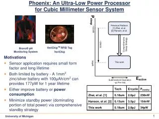
IMPLEMENTATION AND TEST • The proposed temperature sensor has been fabricated in a 0.18μm 1P6M CMOS technology. • The size of the temperature sensor is only 0.2mm2 and the measured power consumption is only 0.9μW at 47℃.
Figure 8 shown the measured digital output of the counter when the temperature was changed from 27℃ to 47℃. The accuracy is within ±1℃ after calibration. • The temperature coefficient of the constant pulse generator is 132ppm.
CONCLUSION • This work presented a novel ultra low power temperature sensor, which is suitable for passive UHF RFID tag chips. • The sensor uses time domain comparing to avoid the bandgap voltage references and traditional ADCs with larger power consumption to achieve ultra low power. • The proposed design has been fabricated in a 0.18μm 1P6M CMOS technology. As shown in the test, the power consumption is only 0.9μW and the accuracy is ±1℃ after calibration.