Download
1 / 1
10 likes | 85 Views
Solenoids. Solenoids. Field (T). Field (T). Radius (m). Radius (m). Length (m). Length (m). 20. 20. 0.4066. 0.4066. Tantalum Rod. Tantalum Rod. S1. S1. 0.1. 0.1. [fixed]. [fixed]. [0.2,0.45]. [0.2,0.45]. [0,20]. [0,20]. Length (m). Length (m). 0.2. 0.2. [fixed].

E N D
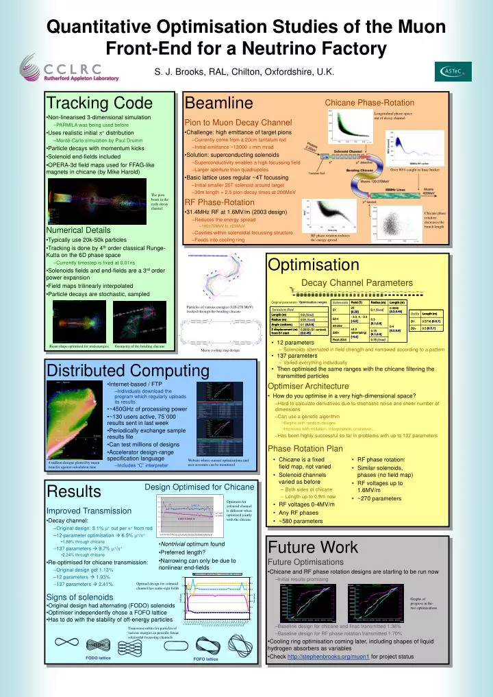
Solenoids Solenoids Field (T) Field (T) Radius (m) Radius (m) Length (m) Length (m) 20 20 0.4066 0.4066 Tantalum Rod Tantalum Rod S1 S1 0.1 0.1 [fixed] [fixed] [0.2,0.45] [0.2,0.45] [0,20] [0,20] Length (m) Length (m) 0.2 0.2 [fixed] [fixed] - - 3.3, 4, 3.3, 4, - - 3.3 3.3 S2 S2 - - 4 4 0.3 0.3 Radius (m) Radius (m) 0.01 0.01 [fixed] [fixed] [ [ - - 5,5] 5,5] [0.1,0.4] [0.1,0.4] Angle (radians) Angle (radians) [0,0.5] [0,0.5] 0.1 0.1 S5 S5 - - S24 S24 0.4 0.4 ±3.3 ±3.3 Z displacement (m) Z displacement (m) 0.2033 (S1 centred) 0.2033 (S1 centred) [0.2,0.6] [0.2,0.6] 0.15 0.15 S25+ S25+ (alternating) (alternating) from S1 start from S1 start [0,0.45] [0,0.45] [0.1,0.4] [0.1,0.4] [ [ - - 4,4] 4,4] Final (S34) Final (S34) 0.15 0.15 [fixed] [fixed] Drifts Drifts Length (m) Length (m) [0.5,1] [0.5,1] D1 D1 0.5718 0.5718 [0.5,1] [0.5,1] D2+ D2+ 0.5 0.5 Quantitative Optimisation Studies of the Muon Front-End for a Neutrino Factory S. J. Brooks, RAL, Chilton, Oxfordshire, U.K. • Tracking Code • Non-linearised 3-dimensional simulation • PARMILA was being used before • Uses realistic initial p+ distribution • Monté-Carlo simulation by Paul Drumm • Particle decays with momentum kicks • Solenoid end-fields included • OPERA-3d field maps used for FFAG-like magnets in chicane (by Mike Harold) • Numerical Details • Typically use 20k-50k particles • Tracking is done by 4th order classical Runge-Kutta on the 6D phase space • Currently timestep is fixed at 0.01ns • Solenoids fields and end-fields are a 3rd order power expansion • Field maps trilinearly interpolated • Particle decays are stochastic, sampled • Beamline • Pion to Muon Decay Channel • Challenge: high emittance of target pions • Currently come from a 20cm tantalum rod • Initial emittance ~13000 p mm mrad • Solution: superconducting solenoids • Superconductivity enables a high focussing field • Larger aperture than quadrupoles • Basic lattice uses regular ~4T focussing • Initial smaller 20T solenoid around target • 30m length = 2.5 pion decay times at 200MeV • RF Phase-Rotation • 31.4MHz RF at 1.6MV/m (2003 design) • Reduces the energy spread • 180±75MeV to ±23MeV • Cavities within solenoidal focussing structure • Feeds into cooling ring Chicane Phase-Rotation Longitudinal phase-space out of decay channel Over 80% caught in linac bucket The pion beam in the early decay channel Chicane phase rotation decreases the bunch length RF phase rotation reduces the energy spread • Optimisation • Optimiser Architecture • How do you optimise in a very high-dimensional space? • Hard to calculate derivatives due to stochastic noise and sheer number of dimensions • Can use a genetic algorithm • Begins with random designs • Improves with mutation, interpolation, crossover… • Has been highly successful so far in problems with up to 137 parameters • Phase Rotation Plan Decay Channel Parameters Optimisation ranges Original parameters / Particles of various energies (120-270 MeV) tracked through the bending chicane • 12 parameters Beam shape optimised for mid-energies Geometry of the bending chicane – Solenoids alternated in field strength and narrowed according to a pattern Muon cooling ring design • 137 parameters Distributed Computing – Varied everything individually • Then optimised the same ranges with the chicane filtering the transmitted particles • Internet-based / FTP • Individuals download the program which regularly uploads its results • ~450GHz of processing power • ~130 users active, 75`000 results sent in last week • Periodically exchange sample results file • Can test millions of designs • Accelerator design-range specification language • Includes “C” interpreter • Chicane is a fixed field map, not varied • Solenoid channels varied as before • Both sides of chicane • Length up to 0.9m now • RF voltages 0-4MV/m • Any RF phases • ~580 parameters • RF phase rotation: • Similar solenoids, phases (no field map) • RF voltages up to 1.6MV/m • ~270 parameters Website where current optimisations and user accounts can be monitored 4 million designs plotted by muon transfer against calculation time • Results • Improved Transmission • Decay channel: • Original design: 3.1% m+out per p+ from rod • 12-parameter optimisation 6.5% m+/p+ • 1.88% through chicane • 137 parameters 9.7% m+/p+ • 2.24% through chicane • Re-optimised for chicane transmission: • Original design got 1.13% • 12 parameters 1.93% • 137 parameters 2.41% • Signs of solenoids • Original design had alternating (FODO) solenoids • Optimiser independently chose a FOFO lattice • Has to do with the stability of off-energy particles Design Optimised for Chicane Optimum for solenoid channel is different when optimised jointly with the chicane • Future Work • Future Optimisations • Chicane and RF phase rotation designs are starting to be run now • Initial results promising • Baseline design for chicane and linac transmitted 1.36% • Baseline design for RF phase rotation transmitted 1.70% • Cooling ring optimisation coming later, including shapes of liquid hydrogen absorbers as variables • Check http://stephenbrooks.org/muon1 for project status • Nontrivial optimum found • Preferred length? • Narrowing can only be due to nonlinear end-fields Optimal design for solenoid channel has same-sign fields Graphs of progress in the two optimisations Transverse orbits for particles of various energies in periodic linear solenoidal focussing channels FODO lattice FOFO lattice