Download
1 / 27
360 likes | 691 Views
Transonic store separation studies on the SAAB Gripen aircraft using CFD. Ingemar Persson and Anders Lindberg. Stockholm, October 18, 2010. Outline of presentation. Introduction Models Computations (CFD and 6-DOF) Results Conclusions. Introduction.

E N D
Transonic store separation studies on the SAAB Gripen aircraft using CFD Ingemar Persson and Anders Lindberg Stockholm, October 18, 2010 www.saabgroup.com
Outline of presentation • Introduction • Models • Computations (CFD and 6-DOF) • Results • Conclusions www.saabgroup.com
Introduction • External stores must be released in a safe and well predicted manner • 6-DOF simulation model to predict store trajectories • SSM includes free-flying store aerodynamics as well as interference aerodynamics • Data collected from complicated and extensive WT-tests using a two-sting-rig • Time and budget limitations lead to alternative ways in achieving store release predictions • Advances in CFD and low cost computer power make computational aerodynamics an interesting alternative www.saabgroup.com
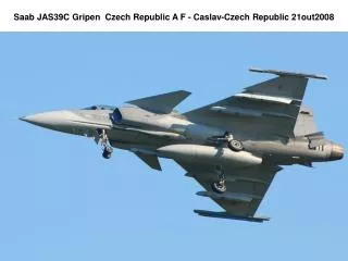
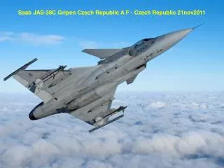
Introduction • SAAB Gripen • Flight condition M=0.9, AoA=1.9 degrees • Payload: Four 227 kg Mk82LD at 2L/2R and 3L/3R • WT: centerline DT300 droptank • FT: centerline FUNK camera pod www.saabgroup.com
Models – CAD models • CATIA v.4 models, imported to ICEM CFD using direct CAD interface • Slight modifications of surface geometry to improve prismatic boundary layer grid • Discrepancy: Pylon 4 not present in CAD/CFD models • Different levels of modelling complexity tried on pylons • Complexity of sway braces • Suspension lugs present or not • Gap distance between payload and pylon uncertain, used 8.7 mm • Both WT and FT configurations modelled www.saabgroup.com
Models – Discrete CFD models • Grid generation using ICEM Tetra/Prism • Captive position and 6 subsequent vertical positions • Tetrahedral grids approximately 4.5-6.5 Mnodes • Mixed tetrahedral / prismatic grids approximately 19-22 Mnodes • Boundary layer grid holding 40 prismatic layers • y+=1 grid, Initial cell height 2e-5 m, expansion factor 1.2 • Far field positioned 10 a/c lengths away from aircraft www.saabgroup.com
Mk82LD in captive position Detail of grid around the bomb fins Grid generation – Detail of mixed tetrahedral / prismatic grid around payload www.saabgroup.com
Computations - General • CFD solution obtained using the EDGE v.4.1.0 fluid flow solver • Inviscid computations utilising a central scheme using JST art.visc. • Viscous computations performed with both central and upwind scheme • Thin shear layer NS equations solved • Turbulence model is Menter SST k-w • RK time integration with agglomorated FAS multigrid conv.acc. • Upwind computations always initiated with 1st order scheme and later switch to 2nd order using a Roe flux difference splitting employing a minmod limiter www.saabgroup.com
Computations – Boundary conditions • Farfield – Riemann invariants • Solid surface – slip / no slip • Engine inlet / outlet – flow through surfaces with prescribed flow • ECS inlet / outlet – flow through surfaces with prescribed flow • Example of RANS computation www.saabgroup.com
Store relative motion depends on Store free flight aerodynamics Mass and inertial data Aircraft interference aerodynamics Aircraft motion during separation ERU force on the store ERU module consists of a gas dynamic model ODE system solved by RK-Merson Solution visualised in SAAB system ICARUS Example from ICARUS Computations – 6-DOF simulation www.saabgroup.com
Flight test – Separation as seen from chase a/c www.saabgroup.com
The first simulation based on WT data from a configuration with a DT300 attached to pylon 5 www.saabgroup.com
Surface pressure field, Euler simulationNote the difference in shock strength. The drop tank results in a large under pressure on the bomb fins which gives a large yawing moment. www.saabgroup.com
Results – Corrective techniques www.saabgroup.com
Results – Corrective techniques www.saabgroup.com
Results – Corrective techniques www.saabgroup.com
Results – Simulation with captive corrections www.saabgroup.com
Results – Based on CFD alone • Grid based approach • Captive and subsequent vertical positions computed (0.0625, 0.125, 0.25, 0.5, 1.0, 2.0 m) • Different complexity of pylon attachment investigated (sway bracer realisation, suspension lugs etc.) • Euler and Navier-Stokes • Different numerical schemes (central and upwind) • Captive absolute condition hard to capture www.saabgroup.com
Example of RANS computation with 0.25 m vertical drop of RHS Mk82LD www.saabgroup.com
Results – Based on CFD alone www.saabgroup.com
Results – Based on CFD alone www.saabgroup.com
Results – Based on CFD alone www.saabgroup.com
Comparison between simulations based on the different settings www.saabgroup.com
Conclusions • Computational aerodynamics is a useful tool when used in a corrective manner • Achieving the correct captive aerodynamic load is of vital importance • Computational aerodynamics as a sole contributor of aero data was not as accurate but can be used as an indicative method • For this case, inviscid physics was ”accurate enough”. Viscous computations did not improve results to motivate the increased work load www.saabgroup.com
www.saabgroup.com www.saabgroup.com