Download
1 / 44
440 likes | 541 Views
Computer Architecture Slide Sets WS 2011/2012 Prof. Dr. Uwe Brinkschulte Prof. Dr. Klaus Waldschmidt. Part 11 Memory Management. The main memory of a processor is usually implemented as semiconductor memory in MOS technology.

E N D
Computer Architecture Slide Sets WS 2011/2012 Prof. Dr. Uwe Brinkschulte Prof. Dr. Klaus Waldschmidt Part 11 Memory Management Computer Architecture – Part 11 –page 1 of 44 – Prof. Dr. Uwe Brinkschulte, Prof. Dr. Klaus Waldschmidt
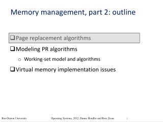
The main memory of a processor is usually implemented as semiconductor memory in MOS technology. Bits are stored statically using so-called flip-flops or dynamically using capacitors in a so-called 1-transistor-cell. The memory is set up as a matrix. The random access is done by the decoders. SRAM Static Random Access DRAM Dynamic Random Access Main Memory Computer Architecture – Part 11 –page 2 of 44 – Prof. Dr. Uwe Brinkschulte, Prof. Dr. Klaus Waldschmidt
Main Memory • The access- and cycle-time of SRAMs is faster than that of DRAMs. • But the area consumption of SRAMs is increased considerably, as six transistors are needed to form a flip-flop. • Due to these characteristics, DRAMs are about ten times slower and cheaper than SRAMs. Computer Architecture – Part 11 –page 3 of 44 – Prof. Dr. Uwe Brinkschulte, Prof. Dr. Klaus Waldschmidt
Setup Principle of a RAM SRAM & row DRAM R S x read write 1 write 0 & & column row 1 1 1 A0 A1 row y … … row (word)decoder … CE: Chip Enable WE: Write Enable OE: Output Enable I/O: Input/Output Data A: Address D: Data UDD: Power supply USS: Ground column memorycell … memory matrix z 1 z address input: row and column address … … 2z 2s 1 1 … column (bit) decoder … s s An-1 sense amplifier CE WE OE control UDD USS I/O buffer .............. D0 D1 Dm I/O-interface data Computer Architecture – Part 11 –page 4 of 44 – Prof. Dr. Uwe Brinkschulte, Prof. Dr. Klaus Waldschmidt
bit 0 bit 1 & & ... Setup of an SRAM R S R S & & & & word 0 wired or & & wired or ... R S R S decoder & & & & word 1 & & ... R S R S & & & & A memory matrix & & & & A: address W: write R: read i: input o: output w r ... 1 1 i0 l0 i1 l1 & & O1 O0 Computer Architecture – Part 11 –page 5 of 44 – Prof. Dr. Uwe Brinkschulte, Prof. Dr. Klaus Waldschmidt
In a DRAM, the information (a bit) is stored in a capacity. After a certain time or when read out the information is lost. Therefore this method of storage is called dynamic – as opposed to the static method, where the bit is represented by the state of a flip-flop. Dynamic semiconductor memories require rewriting the information to the cell after reading it or after a certain time span (some milliseconds). This procedure is called refresh. As a result of the necessity of a refresh, the access time and the cycle time differ observably. General DRAM Principles Computer Architecture – Part 11 –page 6 of 44 – Prof. Dr. Uwe Brinkschulte, Prof. Dr. Klaus Waldschmidt
A chip has only a limited number of connectors. Therefore a reasonable goal is to save on address lines. This is more critical for DRAMs since due to the simple cell structure much larger memory sizes can be realized as for SRAMs Therefore, most DRAMs do this by multiplexing the address and apply it successively in two parts. The synchronization of the address parts is done by the signals RAS (Row Access Strobe) and CAS (Column Access Strobe). The row access time and the column access time sum up to the overall access time. General DRAM Principles Computer Architecture – Part 11 –page 7 of 44 – Prof. Dr. Uwe Brinkschulte, Prof. Dr. Klaus Waldschmidt
RAS (row address strobe) wordselection row address register address column address register read/ write sense amplifier bit-selection and driver CAS (column address strobe) data Block Diagram of a DRAM Computer Architecture – Part 11 –page 8 of 44 – Prof. Dr. Uwe Brinkschulte, Prof. Dr. Klaus Waldschmidt
The access time of a DRAM may be shortened by: The nibble mode When the RAS signal is set, the next bits in row are delivered as well The page mode When the RAS signal is set, the full row (page) is delivered Speeding up DRAM Access Computer Architecture – Part 11 –page 9 of 44 – Prof. Dr. Uwe Brinkschulte, Prof. Dr. Klaus Waldschmidt
The DRAM access characteristics can be improved by several techniques.Newer DRAM variants showing much shorter access times than standard DRAMs. DRAM-Variants EDO-RAM (Extended Data Out) EDO-RAM is dynamic memory supporting address pipelining. An already addressed line is buffered an can be read using the page mode. Computer Architecture – Part 11 –page 10 of 44 – Prof. Dr. Uwe Brinkschulte, Prof. Dr. Klaus Waldschmidt
DRAM-Variants SDRAM (Synchronous DRAM) supports burst access to sequential RAM areas. The access time is approximately that of static RAMs. SDRAMs consist of several banks having the same bit-width as the chip itself. All banks are given the same row address signal simultaneously. A row (page) is spread over several banks. The same page can be accessed repeatedly without being opened again. If a following page is accessed which was not opened, delays occur. Computer Architecture – Part 11 –page 11 of 44 – Prof. Dr. Uwe Brinkschulte, Prof. Dr. Klaus Waldschmidt
Structure of a SDRAM chip column address row address column address counter column address buffer row address buffer refresh counter bank0 bank1 bank2 bank3 input buffer output buffer Data Computer Architecture – Part 11 –page 12 of 44 – Prof. Dr. Uwe Brinkschulte, Prof. Dr. Klaus Waldschmidt
DRAM-Variants RAMBUS (RDRAM) The core of a 64 MB chip consists of e.g. 16 DRAM banks which can be accessed simultaneously. When a DRAM page miss occurs, other accesses may deliver their results instead. The bus clock is 400 MHz and runs at double data rate (DDR). Computer Architecture – Part 11 –page 13 of 44 – Prof. Dr. Uwe Brinkschulte, Prof. Dr. Klaus Waldschmidt
Modern microprocessor systems working on several applications need large amounts of main memory. A cheap method to enlarge the memory capacity is to integrate a mass memory (like a hard disk). The main memory and mass memory are organized to pretend a main memory of nearly unlimited capacity. The available memory area is therefore called virtual memory and the concept is called virtual memory management. Virtual memory Computer Architecture – Part 11 –page 14 of 44 – Prof. Dr. Uwe Brinkschulte, Prof. Dr. Klaus Waldschmidt
Virtual memory main memory (physical memory) virtual memory (addressable memory) physical address ... virtual address ... mass memory Computer Architecture – Part 11 –page 15 of 44 – Prof. Dr. Uwe Brinkschulte, Prof. Dr. Klaus Waldschmidt
A special hardware in the processor, the memory management unit (MMU) translates the virtual addresses generated by the processor to physical addresses in the main memory at runtime. The needed table information is provided by the operating system. In case of a missing data in the main memory, the MMU creates an event to indicate the operating system to load (swap) the missing data from mass memory Memory Management Unit (MMU) main memory CPU MMU virtual address physical address operating system provides table information and loads missing data Computer Architecture – Part 11 –page 16 of 44 – Prof. Dr. Uwe Brinkschulte, Prof. Dr. Klaus Waldschmidt
To keep the memory management overhead low, the virtual memory is organized in blocks. The MMU’s mapping information therefore refers to contiguous address areas instead of single addresses. If the size of the blocks is fixed, we talk about paging. If it is variable depending on the application structure, we talk about segmentation. Address translation Virtual address Physical address block# offset# address translation Computer Architecture – Part 11 –page 17 of 44 – Prof. Dr. Uwe Brinkschulte, Prof. Dr. Klaus Waldschmidt
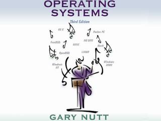
Segmentation virtual address space physical address space • Variable size segments usually belong to tasks • Segments reflect the logical program structure and can be rather large (MBytes) • A task might consist of several segments (e.g. code segment, data segment, stack segment, heap segment) • Segments are either completely swapped in or out segment 1 segment 1 task 1 swapped in segment 2 task 2 segment 4 segment 3 task 3 unused task 4 segment 4 mass memory swapped out Computer Architecture – Part 11 –page 18 of 44 – Prof. Dr. Uwe Brinkschulte, Prof. Dr. Klaus Waldschmidt
Segmentation Address Translation virtual address n bit segment address offset address v bit p bit phys. descriptor- table start address + m bit m bit segment descriptor segment type + physical address physical segment start address m bit m bit segment size access rights segment swapped out ... part of segment descriptor table maintained by the operating system in the main memory Computer Architecture – Part 11 –page 19 of 44 – Prof. Dr. Uwe Brinkschulte, Prof. Dr. Klaus Waldschmidt
An Example for Segmentation 31 23 0 segment# offset# virtual address 8 24 segment table 7937 10258 0 1 2 258 10000 3843 18195 24 bitssegment size 32 bits physical segment start address 255 32 32 + 31 0 pjhysical address Computer Architecture – Part 11 –page 20 of 44 – Prof. Dr. Uwe Brinkschulte, Prof. Dr. Klaus Waldschmidt
An Example for Segmentation mapping of three segments to the physical address space virtual address space physicaladdress space 0 0 7937 Bytes 16M 10000 258 Bytes 7937 Bytes 10258 258 Bytes 1 16M 18195 3843 Bytes 2 22038 3843 Bytes virtual segment# physical base address 16M Computer Architecture – Part 11 –page 21 of 44 – Prof. Dr. Uwe Brinkschulte, Prof. Dr. Klaus Waldschmidt
Pros: Segmentation reflects the logical structure of the application Changing information about a big connected memory area (like its base address, length, access attributes, or status) represented by a segment needs little effort, because only one table entry (the segment descriptor) is affected. The tables are small, as the number of segments is usually small. Segmentation: Diskussion Computer Architecture – Part 11 –page 22 of 44 – Prof. Dr. Uwe Brinkschulte, Prof. Dr. Klaus Waldschmidt
Cons: Segments must be swapped in and out as a whole, even if only a part of them is needed in the main memory. Since segments are of variable size, a suitable free place in main memory has to be found when rolling in a segment This leads to an external fragmentation of the main memory into free and occupied chunks of different sizes. The management of the memory bubbles (free areas) therefore needs additional effort, the so-called garbage collection. Segmentation: Discussion Computer Architecture – Part 11 –page 23 of 44 – Prof. Dr. Uwe Brinkschulte, Prof. Dr. Klaus Waldschmidt
Paging physical address space frame 1 Task 1 frame 2 • A task is spread over many fixed sized pages • Pages are rather small (e.g. 0.5kByte, 1kByte, 2kByte, 4kByte) • Pages are assigned to frames of the same size in physical address space • Consecutive pages might not be assigned to consecutive frames • A task might be partially swapped in frame 3 logical address space frame 4 Task 1 page 1 Task 1 frame 5 task 1 page 2 frame 6 page 3 frame 7 Task 1 page 4 Task 1 frame 8 page 5 frame 9 page 6 frame 10 task 2 Task 1 page 7 Task 1 frame 11 unbenutzt page 8 frame 12 page 9 frame 13 page 10 Task 1 frame 14 task 3 page 11 unbenutzt frame 15 Task 1 page 12 frame 16 unbenutzt frame 17 frame 18 frame 19 frame 20 Task 1 frame 21 unbenutzt frame 22 . . . Computer Architecture – Part 11 –page 24 of 44 – Prof. Dr. Uwe Brinkschulte, Prof. Dr. Klaus Waldschmidt
logical address n bit offset address page address p bit v bit phys. page table start address m bit + m bit c = concatenation c physical address frame number of the page m-p bit m bit page table in main memory Paging Address Translation • due to small page size, the page table might be large Computer Architecture – Part 11 –page 25 of 44 – Prof. Dr. Uwe Brinkschulte, Prof. Dr. Klaus Waldschmidt
logicaladdress page directory address page address offset address page directory c physical address c page table Hierarchical Page Tables • avoids large page tables by splitting them • not all page tables must be swapped in Computer Architecture – Part 11 –page 26 of 44 – Prof. Dr. Uwe Brinkschulte, Prof. Dr. Klaus Waldschmidt
Translation Look Aside Buffer (TLB) logicaladdress • speeds up address translation by caching the latest referenced table entries page directory address page address offset address TLB page directory c physical address c page table Computer Architecture – Part 11 –page 27 of 44 – Prof. Dr. Uwe Brinkschulte, Prof. Dr. Klaus Waldschmidt
Pros: Pages can be stored non-consecutively, so that the available main memory is usable in an optimal way. The management of free memory bubbles is much simpler as the pages/frames are all the same size. There is no external fragmentation. Mechanisms like the garbage collection are not needed. It is easy to change the size of a task at run-time by adding or removing pages Swapping is done more efficiently, as only the actually needed pages of a task have to be kept in the main memory. Paging: Discussion Computer Architecture – Part 11 –page 28 of 44 – Prof. Dr. Uwe Brinkschulte, Prof. Dr. Klaus Waldschmidt
Cons: Changes of information concerning the task (e.g. access attributes) may have to be applied to many page descriptors. The translation tables are much larger than that of segmentation. The last page of a task usually is only partly filled (internal fragmentation) Paging: Discussion Computer Architecture – Part 11 –page 29 of 44 – Prof. Dr. Uwe Brinkschulte, Prof. Dr. Klaus Waldschmidt
Combining Segmentation and Paging logical address segmentation linear address • combines advantages of both worlds • used e.g. in the Pentium family paging physical address Computer Architecture – Part 11 –page 30 of 44 – Prof. Dr. Uwe Brinkschulte, Prof. Dr. Klaus Waldschmidt
When a page or segment fault occurs, the operating system must decide which page/segment should be removed from the main memory to free up space for the page/segment to be swapped in. If the page/segment to be removed was modified in the main memory, it must be written back to the mass memory to keep it up-to-date. If it was not modified, the new page/segment just overwrites it in the main memory. To keep track of the modification state of a page/segment, a status bit is used. This bit is called the modified-bit or dirty-bit. Replacement algorithms are needed at other layers of the memory hierarchy, as well, e.g. between main memory and cache. Replacement Algorithms Computer Architecture – Part 11 –page 31 of 44 – Prof. Dr. Uwe Brinkschulte, Prof. Dr. Klaus Waldschmidt
The system performance highly depends on the strategy by which the pages or segments to be swapped out are selected. Several strategies are possible, e.g. randomly selecting. However it has proved to be preferable to swap out a page/segment which was seldom referenced in the past. This is because a frequently referenced page/segment has a higher probability that it will be needed again soon after being swapped out and therefore would have to be swapped in again, pushing another page or segment out. This is called the locality principle. Replacement Algorithms Computer Architecture – Part 11 –page 32 of 44 – Prof. Dr. Uwe Brinkschulte, Prof. Dr. Klaus Waldschmidt
The best possible replacement algorithm is easy to describe, yet impossible to implement: For every page/segment residing in the main memory it is known how many memory accesses will happen until it is referenced next. If a page/segment fault occurs, the optimal replacement algorithm just swaps out the page with the highest mark. Obviously, this algorithm cannot be implemented, as the operating system has no way to calculate the references in advance. To do this it would have to have a foresight. The Optimal Replacement Algorithm Computer Architecture – Part 11 –page 33 of 44 – Prof. Dr. Uwe Brinkschulte, Prof. Dr. Klaus Waldschmidt
The optimal replacement algorithm has a practical meaning, however: An application can be run on a simulator. During its execution all accesses are logged, so that afterwards, all times of page/segment references are known. They are then used to measure and compare algorithms which actually can be implemented. The Optimal Replacement Algorithm Computer Architecture – Part 11 –page 34 of 44 – Prof. Dr. Uwe Brinkschulte, Prof. Dr. Klaus Waldschmidt
Most page replacement algorithms keep track of which pages/segments were referenced and in which mode (read or write). To do this, two status bits R and M are assigned to every page/segment. R is set if a page/segment was referenced. M is set if a page/segment was modified and therefore must be written back to the mass memory if it is to be pushed out. As these bits are set for every access to the main memory, it is necessary to let the hardware do this. A bit is set until it is reset explicitly by the software. Resetting the R-bit introduces a temporal component to the algorithm: aging. Referenced-Bit and Modified-Bit Computer Architecture – Part 11 –page 35 of 44 – Prof. Dr. Uwe Brinkschulte, Prof. Dr. Klaus Waldschmidt
NRU is a simple algorithm: When a page/segment is loaded to the main memory, R and M are set to 0. R and M are set according to the previously defined rules Periodically all R bits are reset If a page fault occurs, the operating system does a classification (see table). The page/segment to be swapped out is chosen randomly from the lowest non-empty class R (referenced) M (modified) class 0 “0“ “0“ class 1 “0“ “1“ class 2 “1“ “0“ class 3 “1“ “1“ 1. The Not-Recently-UsedReplacement Algorithm (NRU) Computer Architecture – Part 11 –page 36 of 44 – Prof. Dr. Uwe Brinkschulte, Prof. Dr. Klaus Waldschmidt
The basic idea of the FIFO algorithm is to keep all pages/segments in a linked list. When a page/segment is loaded to the main memory, it is appended to this list. If a fault occurs the page/segment at the head of the list is removed. However, the FIFO principle does not consider the frequency of references. In case of a fault always the oldest page/segment is swapped out, regardless if another page/segment was rarely or even never referenced. 2. The First-In-First-Out Replacement Algorithm (FIFO) head tail Computer Architecture – Part 11 –page 37 of 44 – Prof. Dr. Uwe Brinkschulte, Prof. Dr. Klaus Waldschmidt
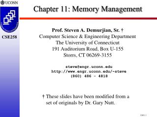
The second-chance replacement algorithm enhances the FIFO algorithm. When a fault occurs, the R-bit of the oldest page/segment is inspected. If it is set, then it gets reset and the page/segment is put to the tail of the list. The page/segment is then treated like newly loaded and therefore gets a second chance. Only the list element at the head of the list whose R-bit is 0 get swapped out. 3 7 8 12 14 15 18 20 0 3 7 8 12 14 15 18 A A oldest youngest oldest youngest A is treated like newly loaded 3. The Second-ChanceReplacement Algorithm swap in timestamp B C D E F G H Computer Architecture – Part 11 –page 38 of 44 – Prof. Dr. Uwe Brinkschulte, Prof. Dr. Klaus Waldschmidt
The maintenance cost of the second-chance algorithm is very high, as it frequently needs inserting and deleting of elements. The clock-page algorithm is more efficient by organizing the elements in a circular list. A pointer references the oldest element. If a fault occurs, the R-bit of the referenced element is inspected. If it is 0 then the element is swapped out, else the bit gets reset. In both cases the pointer advances to the next position. C C D D 4. The Clock Replacement Algorithm A L B K J I E H F G Computer Architecture – Part 11 –page 39 of 44 – Prof. Dr. Uwe Brinkschulte, Prof. Dr. Klaus Waldschmidt
A simple implementation of LRU with hardware assistance can be as follows: The hardware provides a counter having an appropriate bit width. Every page/segment descriptor contains a data field big enough to hold the current value of this counter. For every main memory access the current counter value is written to the descriptor of the affected page/segment. If a fault occurs, the page/segment whose descriptor holds the lowest value is pushed out. However, updating the linked list and finding the descriptor with the lowest value remains costly, even with hardware assistance. 5. The Least-Recently-Used Replacement Algorithm (LRU) Computer Architecture – Part 11 –page 40 of 44 – Prof. Dr. Uwe Brinkschulte, Prof. Dr. Klaus Waldschmidt
Another good replacement algorithm can be achieved by considering the following observation: A page/segment which was frequently referenced up to now, will probably be referenced again in the near future. Contrarily, a page/segment which was only seldom referenced will be referenced in the near future with only a small probability. This observation leads to the so-called least-frequently-used strategy (LFU): If a fault occurs, replace the page/segment which was least frequently referenced. 6. The Least-Frequently-Used Replacement Algorithm (LFU) Computer Architecture – Part 11 –page 41 of 44 – Prof. Dr. Uwe Brinkschulte, Prof. Dr. Klaus Waldschmidt
A full implementation of LFU creates high maintenance costs: It requires keeping a linked list of all pages/segments currently residing in the main memory. The element most frequently referenced will then be put to the head of the list and the element most rarely referenced to the tail of the list. To do this, a counter is associated with every element, counting the number of references to this page/segment. The high cost arises from the need to update the counter and reordering the complete list at every main memory access. Therefore a special (and expensive) hardware or a good approximation in software is needed. 6. The Least-Frequently-Used Replacement Algorithm (LFU) Computer Architecture – Part 11 –page 42 of 44 – Prof. Dr. Uwe Brinkschulte, Prof. Dr. Klaus Waldschmidt
If no full hardware implementation of LFU is available, it can be approximated by software. To do this, a counter is associated to every page/segment residing in the main memory. Periodically (not every main memory access) the R bit of each page/segment is added to the page‘s or segment's counter. In case of a fault the page/segment having the least counter value will be pushed out. This method is called not-frequently-used algorithm (NFU). 7. The Not-Frequently-Used Replacement Algorithm (NFU) Computer Architecture – Part 11 –page 43 of 44 – Prof. Dr. Uwe Brinkschulte, Prof. Dr. Klaus Waldschmidt
LRD is a combination of LRU and LFU It tries to maintain the advantage of LFU keeping frequently used actual elements while avoiding its disadvantage keeping as well old elements very often used a long time ago LRD calculates a reference density of an element by Reference density = number of accesses to element / element age The element with the lowest reference density will be replaced This strategy comes close to the optimal strategy, unfortunately it isvery complex to implement. For each element the swap-in-time and the number of accesses must be stored using e.g. a register and a counter Furthermore, a division operation has to be executed for each element when looking for the element with the lowest reference density 8. The Least-Reference-DensityReplacement Algorithm (LRD) Computer Architecture – Part 11 –page 44 of 44 – Prof. Dr. Uwe Brinkschulte, Prof. Dr. Klaus Waldschmidt