Download
1 / 41
410 likes | 532 Views
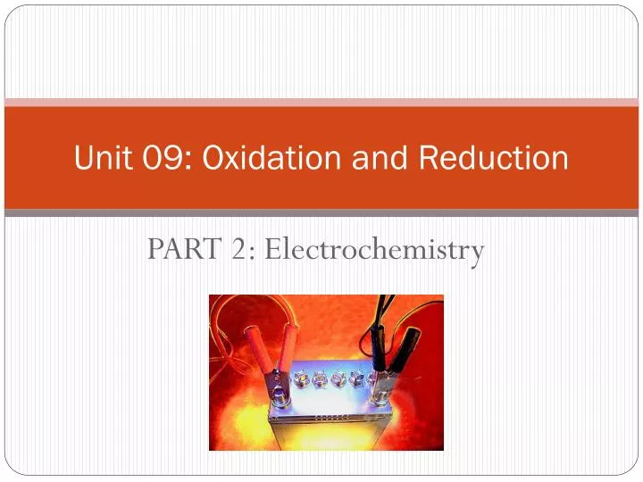
Unit 09: Oxidation and Reduction. PART 2: Electrochemistry. Voltaic Cells. Spontaneous redox rxns can be used to generate an electric current. Half-reactions can be separated so that energy released during a reaction is available as electrical energy instead of being lost as heat.

E N D
Unit 09: Oxidation and Reduction PART 2: Electrochemistry
Voltaic Cells • Spontaneous redox rxns can be used to generate an electric current. • Half-reactions can be separated so that energy released during a reaction is available as electrical energy instead of being lost as heat. • Half-reactions are separated into half-cells, allowing the electrons to flow between them only through an external circuit. • This is known as an elecrochemical, galvanic or a voltaic cell.
Half-cells A simple half-cell is a metal submerged in an aqueous sol’n of it’s own ions.
Half-Cells • In each half-cell, there is a charge separation (because the metal strip of atoms will forms ions by releasing elections that make the surface of the metal negatively charged with respect to the solution), known as electrode potential. • At the same time, ions in the sol’n gain electrons to form metal atoms, so an equilibrium exists. • Zn half-cell: Zn2+(aq) + 2e- Zn(s)
Half-Cells • Consider the Zn/Cu battery… The eq’m position of each determines the size of the electrode potential in the half-cell and depends on the reactivity of the metal.
Half-Cells • Copper is the less reactive metal, so in its half-cell, the eq’m position lies further to the right; thus Cu has less of a tendency to lose electrons than Zn. • Zn half-cell: Zn2+(aq) + 2e- Zn(s) • Cu half-cell: Cu2+(aq) + 2e- Cu(s) -0.76V +0.34V
Half-Cells • Thus there are fewer electrons on the copper metal strip, so it will develop a larger (or less negative) electrode potential than the zinc half-cell. • Zn half-cell: Zn2+(aq) + 2e- Zn(s) • Cu half-cell: Cu2+(aq) + 2e- Cu(s) -0.76V +0.34V
Diagram of a voltaic cell: zinc/copper When the copper and zinc half-cells are connected by an external wire, electrons will have a tendency to flow spontaneously from the zinc half-cell to the copper half-cell because of their different electrode potentials (a.k.a. potential difference). • Cu2+(aq) + 2e-→ Cu(s) • Zn(s)→Zn2+(aq) + 2e-
Diagram of a voltaic cell: zinc/copper When the copper and zinc half-cells are connected by an external wire, electrons will have a tendency to flow spontaneously from the zinc half-cell to the copper half-cell because of their different electrode potentials (a.k.a. potential difference). • Cu2+(aq) + 2e-→ Cu(s) • Zn(s)→Zn2+(aq) + 2e-
Diagram of a voltaic cell: zinc/copper When the copper and zinc half-cells are connected by an external wire, electrons will have a tendency to flow spontaneously from the zinc half-cell to the copper half-cell because of their different electrode potentials (a.k.a. potential difference). • Cu2+(aq) + 2e-→ Cu(s) • Zn(s)→Zn2+(aq) + 2e-
Diagram of a voltaic cell: zinc/copper When the copper and zinc half-cells are connected by an external wire, electrons will have a tendency to flow spontaneously from the zinc half-cell to the copper half-cell because of their different electrode potentials (a.k.a. potential difference). • Cu2+(aq) + 2e-→ Cu(s) • Zn(s)→Zn2+(aq) + 2e-
Diagram of a voltaic cell: zinc/copper When the copper and zinc half-cells are connected by an external wire, electrons will have a tendency to flow spontaneously from the zinc half-cell to the copper half-cell because of their different electrode potentials (a.k.a. potential difference). • Cu2+(aq) + 2e-→ Cu(s) • Zn(s)→Zn2+(aq) + 2e-
Diagram of a voltaic cell: zinc/copper When the copper and zinc half-cells are connected by an external wire, electrons will have a tendency to flow spontaneously from the zinc half-cell to the copper half-cell because of their different electrode potentials (a.k.a. potential difference). • Cu2+(aq) + 2e-→ Cu(s) • Zn(s)→Zn2+(aq) + 2e-
Mnemonic device for you… Big fat red cat! The big fat # (greatest reduction potential) is the site of reduction (cathode)
Standard Electrode Potentials • A voltaic cell generates an electromotive force (emf) as electrons flow from the half-cell with more negative potential to the half-cell with the more positive potential. • Magnitude of voltage depends on the difference in the tendencies of these two half-cells to undergo reduction. • Electrode potential of a single half-cell cannot be measured in isolation, but only when electrons flow as it is linked to another half-cell.
Standard Electrode Potentials Thus, to create a list of relative reducing powers of different half-cells, it is necessary to compare them all with some fixed reference point that acts as a standard for measurement.
Why do we need a standard??? • Analogy: heights of mountains can be compared with each other because each is given a height relative to an agreed zero point (sea level)
Standard Electrode Potentials • Reference standard in electrochemistry = standard hydrogen electrode. • H2(g) 2H+(aq) + 2e- • The hydrogen half-cell is arbitrarily assigned electrode potential = 0 V • This gives us a means to measure and compare the electrode potential of any other half-cell to which it is connected.
Measuring standard electrode potentials Half-cells are connected with hydrogen electrode under standard conditons: • Concentration of all sol’ns = 1.0 mol dm-3 • Pressure of all gases = 100 kPa • All substances used must be pure • Temp = 298 K / 25 C • If half-cell does not include a solid metal, platinum (Pt) is used as the electrode.
Measuring standard electrode potentials Shorthand/line notation:
Calculations involving standard electrode potentials Keep the following in mind: • All E values refer to the reduction rxn. • The E value for the oxidation rxn will be of equal magnitude and opposite sign. • The E values do not depend on the total number of electrons, so do not have to be scaled up or down according to the stoichiometry of the eq’n. • The more positive the E value for a half-cell, the more readily it is reduced. • More negative reduction potential = anode • More positive reduction potential = cathode
1. Calculating the cell potential, Ecell Ecell = Ecathode - Eanode Ecell = Ehalf-cell where reduction occurs - Ehalf-cell where oxidation occurs Example: Calculate the emf for a voltaic cell constructed from a copper half-cell and a silver half-cell. Ecell = +0.34 V – (-0.76V) Ecell = +1.10 V
2. Determining spontaneity of a rxn – plug in values based on way rxn is written. Spontaneous if Ecell = positive Ecell = Ehalf-cell where reduction occurs - Ehalf-cell where oxidation occurs Example: Determine whether the following rxn will be spontaneous under standard conditions: Ni(s) + Mn2+(aq) Ni2+(aq) + Mn(s) Oxidation: Ni(s) Ni2+(aq) + 2e- Reduction: Mn2+(aq) + 2e- Mn(s) Ecell = -1.19 V – (-0.26V) Ecell = -0.93 V Nonspontaneous (negative)
3. Comparing relative oxidizing and reducing power of half-cells • Can be used to confirm order of the reactivity series. • Metals with low E values (most negative) are the strongest reducing agents. • Non-metals with high E values are the strongest oxidizing agents.
Units • SI unit of electric current (I): ampere (A) • SI unit of electric charge (Q): Coulomb (C) amt. of charge transported in 1 sec by a current of 1 amp • Q = I x t • C = A x s • Charge of a single electron = 1.602 x 10⁻¹⁹ C • Charge of one mole of electrons = 96, 485 C mol-1 (Farraday’s constant) • SI unit of potential difference: volt (V) equal to the difference in electric potential between two points on a conducting wire, and defined as the amount of energy (J) that can be delivered by a Coulomb of electric charge (C). • V = J / C
Units • Charge of a single electron = 1.602 x 10⁻¹⁹ C • Charge of one mole of electrons = 96, 485 C mol-1 (Farraday’s constant) Value provided on IB test Constant given on AP test
Electrolytic Cells • An external source of electricity drives non-spontaneous redox rxns. • Electricity is passed through an electrolyte and electrical energy is converted into chemical energy. • Electrolyte: substance which does not conduct electricity when solid, but does conduct electricity when molten or in aqueous solution and is chemically decomposed in the process.
Electrolytic Cells • Example: electrolysis of molten sodium chloride
Electrolytic Cells • Example: electrolysis of molten sodium chloride
Electrolytic Cells • Example: electrolysis of molten sodium chloride
Electrolytic Cells • Note: electrode terminology flips from voltaic to electrolytic (because oxidation always occurs at the anode and reduction at the cathode) as we are forcing the current to flow in the nonspontaneous direction in the electrolytic cell.
Electrolysis of aqueous solutions: be familiar with the following examples – see handout, pp. 350-352 of HL Chemistry (Pearson) • Electrolysis of water • Electrolysis of NaCl(aq) • Electrolysis of CuSO4(aq)
Factors influencing selective discharge during electrolysissee handout, pp. 350-352 of HL Chemistry (Pearson) • Relative E values of the ions • Concentrations of the ions in the electrolyte • Nature of the electrode
Factors affecting the amount of product in electrolysis • Charge of the ion • Current • Duration of the electrolysis
Electroplating: the process of using electrolysis to deposit a layer of metal on top of another metal or other conductive substance. An electrolytic cell used for electroplating has the following features: • An electrolyte containing the metal ions which are to be deposited. • The cathode made of the object to be plated. • Sometimes the anode is made of the same metal which is to be coated because it may be oxidized to replenish the supply of ions in the electrolyte. • Reduction of the metal ions at the cathode leads to their deposition on its surface. The process can be controlled by altering the current and the time according to how thick a layer of metal is desired.
Electroplating • Example: How long must a current of 5.00 A be applied to a solution of Ag+ to produce 10.5 g of silver metal? (Sample exercise 17.9, p. 818) 5.00 A = 5.00 C/sec Ag+ + 1e- → Ag(s) = 31.3 min = 1.88 x 10³ sec
Uses of electroplating • Decorative purposes (gold over silver jewelry; nickel plating of cutlery)
Uses of electroplating • Corrosion control (galvanized iron – zinc deposited on iron to be preferentially oxidized)
Uses of electroplating • Improvement of function (chromium on steel reduces wear of tools, for example)