Download
1 / 68
690 likes | 707 Views
Feedback Amplifiers. Outline. Introduction The general feedback structure Some properties of negative feedback The four basic feedback topologies The series-shunt feedback amplifier The series-series feedback amplifier The shunt-shunt and shunt-series feedback amplifier.

E N D
Outline • Introduction • The general feedback structure • Some properties of negative feedback • The four basic feedback topologies • The series-shunt feedback amplifier • The series-series feedback amplifier • The shunt-shunt and shunt-series feedback amplifier
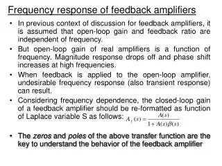
The stability problem • Stability study using bode plot • Frequency compensation
Introduction • It’s impossible to think of electronic circuits without some forms of feedback. • Negative feedback • Desensitize the gain • Reduce nonlinear distortion • Reduce the effect of noise • Control the input and output impedance • Extend the bandwidth of the amplifier
The basic idea of negative feedback is to trade off gain for other desirable properties. • Positive feedback will cause the amplifier oscillation.
The General Feedback Structure This is a signal-flow diagram, and the quantities x represent either voltage or current signals.
The General Feedback Equation • Closed loop and open loop • Closed loop gain • Feedback factor β • Loop gain Aβ • Amount of feedback (1+ Aβ)
Some Properties of Negative Feedback • Gain desensitivity • Bandwidth extension • Noise reduction • Reduction in nonlinear distortion
The Four Basic Feedback Topologies • Voltage amplifier---series-shunt feedback voltage mixing and voltage sampling • Current amplifier---shunt-series feedback Current mixing and current sampling
Transconducatnce amplifier---series-series feedback Voltage mixing and current sampling • Transresistance amplifier---shunt-shunt feedback Current mixing and voltage sampling
The Series-Shunt Feedback Topologies voltage-mixing voltage-sampling (series–shunt) topology
The Amplifier with Series-Shunt Feedback voltage-mixing voltage-sampling (series–shunt) topology
The Shunt-Series Feedback Topologies current-mixing current-sampling (shunt–series) topology
The Amplifier with Shunt-Series Feedback current-mixing current-sampling (shunt–series) topology
The Series-Series Feedback Topologies voltage-mixing current-sampling (series–series) topology
The Amplifier with Series-Series Feedback voltage-mixing current-sampling (series–series) topology
The Shunt-Shunt Feedback Topologies current-mixing voltage-sampling (shunt–shunt) topology
The OP Amplifier with Shunt-Shunt Feedback current-mixing voltage-sampling (shunt–shunt) topology
The Series-Shunt Feedback Amplifier • The ideal situation • The practical situation • summary
A unilateral open-loop amplifier (A circuit). • An ideal voltage mixing voltage sampling feedback network (β circuit). • Assumption that the source and load resistance have been included inside the A circuit.
The Ideal Situation Equivalent circuit. Rif and Rof denote the input and output resistance with feedback.
Input and Output Resistance with Feedback • Input resistance In this case, the negative feedback increases the input resistance by a factor equal to the amount of feedback.
Output resistance In this case, the negative feedback reduces the output resistance by a factor equal to the amount of feedback.
The Practical Situation • Block diagram of a practical series–shunt feedback amplifier. • Feedback network is not ideal and load the basic amplifier thus affect the values of gain, input resistance and output resistance.
The Practical Situation The circuit in (a) with the feedback network represented by its h parameters.
The Practical Situation The circuit in (b) with h21 neglected.
The Practical Situation • The load effect of the feedback network on the basic amplifier is represented by the components h11 and h22. • The loading effect is found by looking into the appropriate port of the feedback network while the port is open-circuit or short-circuit so as to destroy the feedback.
If the connection is a shunt one, short-circuit the port. • If the connection is a series one, open-circuit the port. • Determine the β.
Summary • Ri and Ro are the input and output resistances, respectively, of the A circuit. • Rif and Rof are the input and output resistances, respectively, of the feedback amplifier, including Rs and RL. • The actual input and output resistances exclude Rs and RL.
Example of Series-Shunt Feedback Amplifier • Op amplifier connected in noninverting configuration with the open-loop gain μ, Rid and ro • Find expression for A, β, the closed-loop gain Vo/Vi , the input resistanceRinand the output resistanceRout • Find numerical values
The Series-Series Feedback Amplifier • The ideal situation • The practical situation • summary
The Ideal Situation Trans conductance gain
The Ideal Situation Tranresistance feedback factor
Input and Output Resistance with Feedback • Input resistance In this case, the negative feedback increases the input resistance by a factor equal to the amount of feedback.
Output resistance In this case, the negative feedback increases the output resistance by a factor equal to the amount of feedback.
The Practical Situation Block diagram of a practical series–series feedback amplifier.
Feedback network is not ideal and load the basic amplifier thus affect the values of gain, input resistance and output resistance.
The Practical Situation The circuit of (a) with the feedback network represented by its z parameters.
The Practical Situation A redrawing of the circuit in (b) with z21 neglected.
The Practical Situation • The load effect of the feedback network on the basic amplifier is represented by the components Z11 and Z22. • Z11 is the impedance looking into port 1 of the feedback network with port 2 open-circuited.
Z22 is the impedance looking into port 2 of the feedback network with port 1 open-circuited. • Determine the β.
Summary • Ri and Ro are the input and output resistances, respectively, of the A circuit. • Rif and Rof are the input and output resistances, respectively, of the feedback amplifier, including Rs and RL.