Download
1 / 12
120 likes | 136 Views
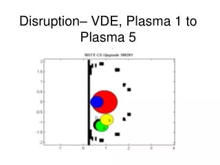
S. Kruger, D. Schnack (SAIC) April 27, 2004 Sherwood Fusion Theory Meeting, Missoula, MT. NIMROD Simulations of a DIII-D Plasma Disruption. DIII-D SHOT #87009 Observes a Plasma Disruption During Neutral Beam Heating At High Plasma Beta. Callen et.al, Phys. Plasmas 6, 2963 (1999).

E N D
S. Kruger, D. Schnack (SAIC) April 27, 2004 Sherwood Fusion Theory Meeting, Missoula, MT NIMROD Simulations of a DIII-D Plasma Disruption
DIII-D SHOT #87009 Observes a Plasma Disruption During Neutral Beam Heating At High Plasma Beta Callen et.al, Phys. Plasmas 6, 2963 (1999)
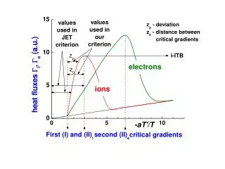
Free-Boundary Simulations Models “Halo” Plasma as Cold, Low Density Plasma • Typical DIII-D Parameters:Tcore~10 keV Tsep~1-10 eVncore~5x10¹⁹ m-3 nsep~ 1018 m-3 • Spitzer resistivity: h~T-3/2 • Suppresses currents on open field lines • Large gradients 3 dimensionally • Requires accurate calculation of anisotropic thermal conduction to distinguish between open and closed field lines
Goal of Simulation is to Model Power Distribution On Limiter during Disruption • Plasma-wall interactions are complex and beyond the scope of this simulation • Boundary conditions are applied at the vacuum vessel, NOT the limiter. • Vacuum vessel is conductor • Limiter is an insulator • This is accurate for magnetic field: • Bn=constant at conducting wall • Bn can evolve at graphite limiter • No boundary conditions are applied at limiter for velocity or temperatures. • This allows fluxes of mass and heat through limiter • Normal heat flux is computed at limiter boundary
Free-Boundary Simulations Based on EFIT Reconstruction • Pressure raised 8.7% above best fit EFIT • Above ideal MHD marginal stability limit • Simulation includes: • n = 0, 1, 2 • Anisotropic heat conduction(with no T dependence)kpar/kperp=108 • Ideal modes grow with finite resistivity (S = 105)
First Macroscopic Feature is 2/1 Helical Temperature Perturbation Due to Magnetic Island • Island result of 1/1 and 3/1 ideal perturbation causing forced reconnection
Magnetic Field Rapidly Goes Stochastic with Field Lines Filling Large Volume of Plasma • Region near divertor goes stochastic first • Islands interact and cause stochasticity • Rapid loss of thermal energy results. Heat flux on divertor rises
Maximum Heat Flux in Calculation Shows Poloidal And Toroidal Localization • Heat localized to divertor regions and outboard midplane • Toroidal localization presents engineering challenges - divertors typically designed for steady-state symmetric heat fluxes • Qualitatively agrees with many observed disruptions on DIII-D
Investigate Topology At Time of Maximum Heat Flux • Regions of hottest heat flux are connected topologically • Single field line passes through region of large perpendicular heat flux. Rapid equilibration carries it to divertor • Complete topology complicated due to differences of open field lines and closed field lines
Initial Simulations Above Ideal Marginal Stability Point Look Promising • Qualitative agreement with experiment: ~200 microsecond time scale, heat lost preferentially at divertor. • Plasma current increases due to rapid reconnection events changing internal inductance • Wall interactions are not a dominant force in obtaining qualitative agreement for these types of disruptions.
Future Directions • Direct comparison of code against experimental diagnostics • Increased accuracy of MHD model • Temperature-dependent thermal diffusivities • More aggressive parameters • Resistive wall B.C. and external circuit modeling • Extension of fluid models • Two-fluid modeling • Electron heat flux using integral closures • Energetic particles • Simulations of different devices to understand how magnetic configuration affects the wall power loading
Conclusions NIMROD’s Advanced Computational Techniques Allows Simulations Never Before Possible • Heating through b limit shows super-exponential growth, in agreement with experiment and theory in fixed boundary cases. • Simulation of disruption event shows qualitative agreement with experiment. • Loss of internal energy is due to rapid stochastization of the field, and not a violent shift of the plasma into the wall. • Heat flux is localized poloidally and toroidally as plasma localizes the perpendicular heat flux, and the parallel heat flux transports it to the wall.