Download
1 / 39
410 likes | 582 Views
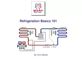
HVACR317 – Refrigeration. Commercial Defrost Sequence. Diagram 1. CFM. Description of Diagram 1. The first diagram represents a typical self-contained reach-in box. It is a low-temp system using hot gas defrost. The compressor is CSIR.

E N D
HVACR317 – Refrigeration Commercial Defrost Sequence
Diagram 1 CFM
Description of Diagram 1 • The first diagram represents a typical self-contained reach-in box. • It is a low-temp system using hot gas defrost. • The compressor is CSIR. • The LAC (low ambient control) would be used if the condensing unit is installed outdoors. • The run cap is optional.
Description of Diagram 2 • Like any system, fan, fan, and compressor will sequence in parallel. • The start cap will provide the required torque to the start winding.
Description of Diagram 3 • The BEMF energizes the relay and drops out the start cap. • The system will cycle normally on the (Honeywell/White Rogers/Johnson Controls) remote bulb thermostat.
Description of Diagram 4 • When the box temperature reaches 0 - 10°F (typical setting), the thermostat opens. EFM and TM continue to run.
Description of Diagram 5 & 6 • When the timer switches to defrost, the compressor stays on and HGS energizes. • The EFM is de-energized in defrost.
Description of Diagram 9 • This system is also low temperature, but using electric defrost. • This type of system has an evaporator fan “delay” sequence. • It uses two “DTT” type controls. • It also has the ability to disengage the timer out of defrost. • Step by step sequence is coming up.
Description of Diagram 10 • Just like the last system: fan, fan, and compressor are running. • The DTC timer is line-to-line (like the last system). • A different type (or model) DTC is used; notice the extra terminals on the timer. • The device between 3 and X is a solenoid (more on that later).
Description of Diagram 11 • The only path is through the heater and “limit”; all else is off. • The limit “act as as” a DTT (like the domestic units). But it has a higher temperature (cut-out) rating than the domestic types. It is basically a high temperature safety. The “actual” DTT is the SPDT one just below the “limit.”
Description of Diagram 12 • When the SPDT DTT senses that the evaporator coil is warm enough, it will switch up to the top circuit, completing a path to the “clutch solenoid” on the DTC. • The solenoid will swap the contacts back into refrigeration mode (no waiting).
Description of Diagram • The evaporator fan has not come on yet due to the warm evaporator coil. • When the DTT cools back down, the switch will drop back in and the evaporator fan will restart. • The purpose of this control (and sequence) is to prevent a “hot pull-down” situation after each defrost cycle.
Diagram 14 Hot pull-down example: Presently, the system is running normal (R134A). The system pressures will generally run 5 to 20 psig.
Diagram 15 When the system goes into defrost, the evaporator coil heats up and thepressures are basically equalized.
Diagram 16 When defrost is terminated, the extreme heat load on the coil could cause an overload on the electrical circuit and trip a breaker. Delaying the EFM is one way to keep the pressures down at initial startup.
Diagram 17 Evaporator gets cold, EFM goes on.
Description of Diagram 18 • Like all (domestic OR commercial) automatic defrost systems, this defrost circuit can be terminated by time and / or temperature. • The main advantage in using this type of timer is the refrigeration mode can be instantly brought back on if the DTT duration lasted just a few minutes.
Description of Diagram 19 • If the SPDT DTT should fail, the limit will provide a lock-out condition if an overheating condition occurs.
Diagram 20 Electric defrost reminders: the element is either on or below the evaporator coil. DTT and limit are both located on evaporator coil.
Description of Diagram 21 • This system is a medium temperature application (EFM is line-to-line). • The defrost cycle simply shuts down the compressor circuit (sometimes done in the late evening hours). A simple timer is used. • The LP switch is used as a temperature control (not a great way to go, but it is common).
Description of Diagram 22 • Using an LP switch as a thermostat: • Set the LP switch to its recommended settings (C.I. and C.O.); attach gauges. • Place a thermometer in the box and close the door. • When the box reaches the desired temperature (e.g., 35°F), set the C.O. of the LP switch to the low side pressure shown on the gauge.
Description of Diagram 23 • High or medium temperature system • Uses off cycle defrost. • “Off cycle” defrost can be set up by adjusting the LP switch differential higher than normal. • The 30 psig differential allows sufficient time for defrost.