Download
1 / 31
310 likes | 437 Views
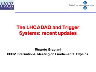
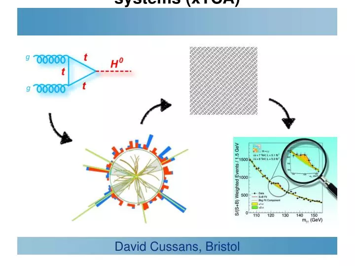
Future Hardware for Trigger and DAQ systems (xTCA). David Cussans, Bristol. Science Motivation. 2008. (100k) Haystacks. 1GHz. 1MHz. 2009. 1kHz. Event rate. Cross-section (interaction probability). 2010. 1Hz. 1/hr. 2011-2. 1/wk. Needle. ‘Typical’ 2012 Bunch Crossing.

E N D
Future Hardware for Trigger and DAQ systems (xTCA) • David Cussans, Bristol
Science Motivation 2008 (100k)Haystacks 1GHz 1MHz 2009 1kHz Event rate Cross-section(interaction probability) 2010 1Hz 1/hr 2011-2 1/wk Needle
Detector Design • LHC detector mission • Find and measure incredibly rare events... (1/hr) • Against almost indistinguishable background of common events (1kHz) • In an environment of incredibly high-rate background (1GHz) • Detector characteristics • Fast response time • Unique crossing-ID required -> 25ns time resolution • Large area and hermeticity; lowest possible material for inner detectors • High granularity • Efficient pattern recognition -> For low occupancy -> 10k’s to M’s of channels • Good resolution, low noise, high dynamic range • Energy resolution in calorimetry; (interpolated) position information in tracking • Environment for on-detector electronics • Highly constrained in terms of space, cooling, access, services • Electromagnetically noisy & high radiation dose in places
Front-End Electronics • e.g. CMS ECAL front end electronics (UK development) • ~80000 channels, 40Ms/s, 12b resolution, 16 b dynamic range • Based on two custom rad-hard CMS ASICs, 0.25u technology • Along with carefully qualified commercial optoelectronics, sensors Digital sampling Pipeline storage Local processing Trigger / DAQoutputs Analogue VFE Control / timing
On Detector Electronics • Design dictated by need to fit in detector and cope with environment.
Off Detector Electronics • Receive data from detector, filter/process, send for storage • Different constraints from on-detector • Can use standard format electronics • Sub-racks housed in larger racks ( sub-racks frequently 19-inches ). • Racks provide power, cooling • Standards change: NIM (1966), CAMAC (1976), FASTBUS (1986), VMEp (1998), xTCA(20xx) ..... • xTCA for HEP proposed at least ten years ago • ( e.g.An Initial Look at a CMS Level-1 Trigger for an Upgraded LHC, D.Cussans et. al.,10th Workshop on Electronics for LHC and Future Experiments, Boston, MA, USA, 13 - 17 Sep 2004, pp.73-76 DOI 10.5170/CERN-2004-010.73 ) • ... but only in last few years has “critical mass” developed.
Why Change? • Current generation of experiments mainly use VME. Why change? • Chasing more massive particles and smaller cross-sections --> need larger machines producing (much) more data. • Last decade revolution in analog, digital, communication technologies opened up new opportunities. • Parallel multi-drop bus --> point-to-point gigabit serial links. • Follow lead from other areas: PCI-->PCIe , Parallel printer --> USB, PATA--> SATA • Programmable FPGA’s allow much more functionality than discrete logic components. Micro-controllers now cheap • Multilayer board design enables Gigabit backplanes >10 GHz bandwidth • –Integrated SERDES communications obsolete parallel bus backplanes • –LVDS balanced multi Gbps backplanes minimize discrete switch blades • –Intelligent platform management diagnoses enterprise wide problems to board level, initiates corrective action • –Redundant architectures => shelf Availability of 5 nines or better (0,99999)
Acknowledgements • Slides/material taken from • Introduction to MicroTCARay Larsen SLAC MicroTCA Review June 4-5, 2012 • xTCA interest grouphttps://twiki.cern.ch/twiki/bin/view/XTCA/WebHome • Mark Pessaresi (FC7) , Andy Rose, Greg Isles (MP7) • Dave Newbold (IPBus)
Will xTCA dissapear? • ATCA (and especially uTCA) new standard, but don’t look as if they are “here today, gone tomorrow”
Currently Vadatech VT892 quite common in CMS ( variant with vertical airflow )
uTCA for Physics (MTCA.4) • New variant to allow rear-transition modules ( RTM)
Examples of uTCA Board • CMS-heavy (apologies) • Could find many more examples from XFEL, FAIR, etc. • Module aimed at test-bench , beam-test work: GLIB • Module aimed at being a “Front End” board that receives data from detector (FC7) • Module aimed at data processing for e.g. trigger (MP7)
FC7 Prototype Front-end AMC • ~10GHz (MP7) • Good performance (weave misaligned with PCB) • Constant low dielectric loss tangent - EPSI-N4000 13 Nelco • 16 layers
FC7 - Input from Detector • Custom input circuitry on “FPGA Mezzanine Cards”
Generic uTCA Test-platform (GLIB,CERN) • Test-bench , beam-test • Two FMC (FPGA Mezzanine Card) site, SFP cages Stefan Haas, MTCA Workshop, DESY, 12. Dec. 2012
Generic uTCA Test-platform (GLIB,CERN) Stefan Haas Stefan Haas, MTCA Workshop, DESY, 12. Dec. 2012 • Available from CERN • Firmware/software skeleton available (uses IPBus)
CMS uTCA Trigger Processor: MP7 • MP7 card: building block for L1 and DAQ systems • Large Virtex-7 series FPGA (6 Billion transistors); 144Mb fast RAM • 1.4Tb/s of low-latency IO on optical links; 50Gb/s backplane IO • Integrated into industry-standard uTCA software / hardware environment • Will future L1 / FE look more like a commercial switch fabric? A. Rose, Imperial
Setup and Control • Current generation of VME crates typically use VME backplane to set-up/configure boards. • Detector data moved around on custom back-plane/ rear-transition-modules • Need to replace this functionality in an xTCA system • One solution is IPBus • Developed for use in CMS upgrades. • Now being adopted by several other experiments
IPBus • IPbus is a simple, IP-based control protocol • Originally created by Jeremy Mans, et al in 2009/2010 • S/w and f/w development is being done by a UK collaboration University of Bristol and Imperial College London, Rutherford Appleton Laboratory • Protocol describes basic transactions needed to control h/w Read/write, non-incrementing read/write, etc, etc. • UDP is the recommended transport implementation • Easiest to implement in firmware • Uses relatively few FPGA resources • Interface inside FPGA looks like a A32/D32 bus. (sub-set of Wishbone) • See https://svnweb.cern.ch/trac/cactus
Board Start-up (MMC) • ATCA, uTCA boards need to negotiate with power supply when inserted in crate. • Allows hot-swap of boards • means that without MMC an AMC won’t do anything when inserted in crate. • Strongly recommend: get hold of somebody else’s code or hardware for MMC. See e.g. https://espace.cern.ch/ph-dep-ESE-BE-uTCAEvaluationProject/MMC_project/default.aspx
Summary • Prediction is very difficult, especially about the future • (ascribed to Neils Bohr ) • .... but it does look like the next generation of off-detector electronics for large HEP experiments will use xTCA • Has reached critical mass. Baseline for CMS upgrades, used for XFEL, at FAIR. • High performance, but a rather complex system • Use off-the-shelf components where possible • e.g. MMC, setup/control firmware