Download
1 / 21
210 likes | 295 Views
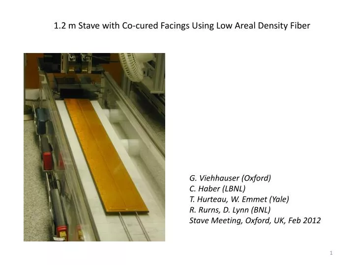
1.2 m Stave with Co-cured Facings Using Low Areal Density Fiber. G. Viehhauser (Oxford) C. Haber (LBNL) T . Hurteau , W. Emmet (Yale) R. Rurns , D . Lynn (BNL) Stave Meeting, Oxford, UK, Feb 2012. New Co-Cure Experiments at LBNL.

E N D
1.2 m Stave with Co-cured Facings Using Low Areal Density Fiber G. Viehhauser (Oxford) C. Haber (LBNL) T. Hurteau, W. Emmet (Yale) R. Rurns, D. Lynn (BNL) Stave Meeting, Oxford, UK, Feb 2012
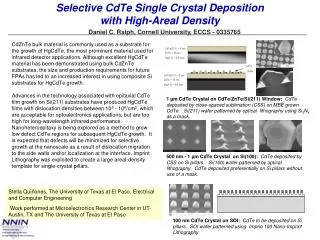
New Co-Cure Experiments at LBNL • 0-90-0 is a better configuration for mechanical performance but curvature issue is more acute (tight bend across cable) • Have studied co-cure on a curved template, sized to compensate for bend, worked well on a stavelet cable • In the process of co-curing two full cables in this way in order to laminate a full stave • Pre-co-cure metrology complete Cable co-cured flat Cure inside 9.5 inch pipe result
Facing challenges for stave cutting facings Twisted/bowed facing. We were not able to hold down on our vacuum fixture for cutting (but our vacuum fixture was poor. Remaking it might work) Kapton side is flat across CF-to-kapton transition Targets proved useful when we cut the facings Different thickness on CF-only side due to kapton cable
Pre-Cut Facing Thickness Measurements Note: All measurements in microns Approximate measurement locations Serial Power Ground return clearly seen on CF side of facing as a raised ridge, but not so much seen in thickness data
New Cut Facing Width • Previous specification on facings for old 1.3 meter stave was 120 mm minimum, and 120.25 mm maximum, and we achieved this. • For this stave we specificed 120.5 mm minimum, 121 mm maximum due to difficulty in achieving this we the co-cured facings • We had also anticipated such a change in tolerance when we redesigned the bracket and the angle of its contact points
Cutting the facings • In the end we clamped down the facings and used a straight-edge and razor • The edge is not so nice but acceptable • In the future would still prefer rotary fine tooth saw and vacuum chuck, but we ran out of time to make this work
Cut Facing Widths One facing was in tolerance, one slightly over. But this was ok because we still have plenty of clearance from jig supports (as well as bracket supports) Facing widths (in mm) Note: facings from LBNL were numbered 1 and 3, not 1 and two
Note that our support design has cf tubes centers spaced 119 mm, If aluminum was more narrow the gluing would be on facing slope
Gluing the CF Tubes Side Rails • To keep facing flat this step and all the following glue steps we had to use lead weights to keep the bowed facing flat. • Bow was mostly in transverse direction
Pre-Gluing the Honeycomb Post-Gluing the Honeycomb
Post Final Facing Attachment • Stave became flatter (measurements to follow) • 2nd Facing to CF pipes glue attachment was not ideal. Will fix, but will need to improve process in the future
Stave Component Weights Co-cured 1.2 m Stave Weights Co-cured Facing Component Weights [g] • Used lighter ss pipes in co-cured stave. • If directly comparing, main mass improvement is 40 grams in carbon fiber facings Previous 1.3 meter stave weights, no kapton bus
4 Point Support Stave Profile, Side 3 (Flattened in Software)
Final Thoughts on Assembly with Co-cured Facings • Twist creates some problems, mostly for holding facing flat during cutting and grinding • We might prefer a wider bus (see bottom) to create a uniform facing thickness • We did not really address alignment issues (top facing to bottom, for example). • However, all of these problems seem manageable and most glue steps were no more difficult than with flat facings and only required more weight (lead bricks) to keep things flat • Possibly would prefer extended transverse bus for constant thickness • Metallization may be used to indicate cut line