Download
1 / 27
270 likes | 340 Views
0. The µWave SDR. By Jonathan Naylor, ON/G4KLX. 1. What Is The µWave SDR?. Cheap access to microwaves Use the best of modern technology DSP to give great performance Small form factor for remote mounting Keep it simple - most microwave ops aren’t computer specialists. 2. The Team.

E N D
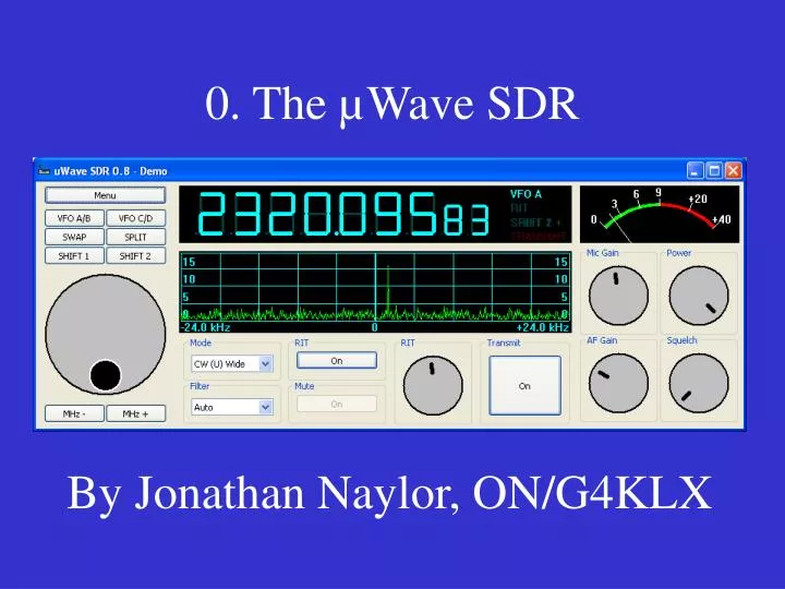
0. The µWave SDR By Jonathan Naylor, ON/G4KLX
1. What Is The µWave SDR? • Cheap access to microwaves • Use the best of modern technology • DSP to give great performance • Small form factor for remote mounting • Keep it simple - most microwave ops aren’t computer specialists
2. The Team • Neil Whiting, G4BRK • Chris Bartram, GW4DGU • Jonathan Naylor, ON/G4KLX • Grant Hodgson, G8UBN • Tobias Weber, DG3YEV
PC Switch 3. The Concept TX µWSDR 1 RX TX µWSDR 2 RX
4. Unified Hardware • Use the latest commercial IC’s/module’s • Same devices across bands • Two part hardware, a common back-end and a band specific front-end • Together Eurocard sized to fit into standard extrusions/cases
5. Front-Ends • Basic specifications: 100 - 200mW RF output 2 - 3dB Noise figure • Simplifies design, reduces cost and engineering complexity • Fits in well with modular designs • Can be used barefoot and still be effective
6. Front-End Block Diagram RF In I/Q Out BPF LPF 10 MHz Osc. Control RF Out I/Q In BPF Control Out Control In
7. Front-End Specifics 1/2 • Single Fraction-N synthesizer chip chosen, the LMX 2486 • Divided for lower bands, thereby reducing phase noise • External high quality 10 MHz source is possible • Commercial of home made VCOs
8. Front-End Specifics 2/2 • Highly integrated RX and TX mixers: RX – LT 5575, LT 5517 TX – ADL 5372, ADL 5385 • Three layer PCB, oscillator on one side, RX and TX chains on the other • Commercial or home made bandpass filters
9. Design Challenges • Microwave band activity areas are narrow, but they may not be the same worldwide 23cms – 1269/1296 MHz 13cms – 2304/2308/2320/2400/2424 MHz 9cms – 3400/3456 MHz • This complicates the design of VCOs and bandpass filters
10. Back-End • Interface between the PC and the Front-End • One per front-end, tightly integrated • Converts base band to ethernet packets and vice versa • Takes commands to control the oscillator and external devices • General purpose CPU for flexibility
11. Back-End Block Diagram I/Q In ADC AKM5394a DAC/ Clock PCM1740E I/Q Out CPU AT91SAM7X256 Ethernet Osc. Control Control Out
12. Back-End Hardware • CPU is a 60 MHz ARM7 core with integrated Ethernet, programmed in C • ADC is AKM5394a operating at either 48 or 96 Ksps • DAC + Clock is PCM1740E, feeds clock to the ADC, speed under software control
13. Back-End Software • Implements a complete UDP/IP stack • Simple command interpreter • Possibility of hardware AGC
14. The Ethernet Protocol • All messages use UDP/IP • All messages have a two character identifier • Data messages have a sequence number to discard out-of-order packets, no retries • Command messages have explicit ACK/NAK • Command messages are transported with a simple stop-and-wait protocol
15. Why Ethernet? • Longer distances than USB, important for /P and remote mounting of hardware • Less HF interference than USB • Simple to extend with fibre optic • A more portable API on computers
16. µWave SDR Software • A suite of four programs: The GUI SDRSetup GUISetup SDRHelp • Very simple to install and use • Completely cross platform, Windows, Linux and Mac OS X
17. SDRSetup • Sets up the UWSDR hardware
18. GUISetup • Creates or changes an instance of the GUI • Sets up external connection information, dependent on the type of SDR chosen
19. SDRHelp • Help available for the other programs • Available from within the GUI
21. GUI Features • Uncluttered design and easy to use • Looks similar to existing radios • Runs on small-ish computers • Supports multiple hardware types: UWSDR SoftRock (RX and RXTX) Demo mode
22. GUI Internals • DSP core based on DttSP but converted to C++ • Removed esoteric features • Added Weaver method • I/O via interfaces making the addition of new hardware simple • More tightly integrated than DttSP, more like PowerSDR
23. GUI Usage • Less used features are hidden away, similar to the IC-706 • Spectrum display is adjustable • S/Power Meter is adjustable • CW/Voice keyer • Has the concept of default bandwidth, AGC speed and tuning speed per mode • Target audience are not computer geeks
24. 3cms SoftRock RXTX? • Fixed LO based on WiMAX VCO and fractional-N synthesizer • Passive bi-directional mixer • Integrated patch antenna for dish mounting -6 dBm RF output (250 µW) 10 dB noise figure • Great for /P use on hills/mountains
25. µWave SDR Progress • Software is mature and in use on-air with SoftRocks • Back-end is progressing well, currently evaluating new Ethernet hardware • Front-Ends are not so advanced
26. Contact • Software is under the GPL • Hardware will probably use the TAPR OHL • If you would like to help the µWave SDR project, either hardware or software Web page: http://www.uwsdr.net E-mail: naylorjs@yahoo.com