Download
1 / 24
240 likes | 287 Views
DFD. IT323 - Software Engineering 2 Tutorial. Decomposition Style. Context Diagram. Shows the boundaries of the system Shows the overall business process as just ONE process Shows all the outside entities that receive information from or contribute information to the system No Data store.

E N D
DFD IT323 - Software Engineering 2 Tutorial
Context Diagram • Shows the boundaries of the system • Shows the overall business process as just ONE process • Shows all the outside entities that receive information from or contribute information to the system • No Data store
Level 0 Diagram • Shows all the processes that comprise the overall system • Shows how information moves from and to each process • Adds data stores
Level 1 Diagram • Shows all the processes that comprise a single process on the level 0 diagram • Shows how information moves from and to each of these processes • Level 1 diagrams may not be needed for all level 0 processes
Guidelines for Drawing a Context • Read the case study from start to finish a number of times until you have a fair idea of what the system as a whole does. • Try to make a list of potential external entities. A person or place is an external entity under two conditions. • Firstly, if it gives something to the system without explanation of the processing involved in its creation. • Secondly, if it receives something from the system with no explanation of what it does with it. • Establish what data flows are sent to external entities from the system and what data flows are received into the system from them. • Having identified external entities and flows to and from them, the context diagram can be drawn.
Guidelines for Drawing Level 0 • Take one sentence at a time and decide if it is background information or if it is an activity which must be represented by a process in the diagram. Processes can be identified by the verb in the sentence. • Make a list of all potential processes • group these potential processes so that you end up with approximately 3 to 10 processes. • Identify and list data flows • these are generally documents but could also be phone calls, physical items such as goods etc. Anything that moves around a system can be considered a data flow. • Identify and list data stores. • Having identified all the components of the DFD, draw the diagram using the appropriate conventions (notation). • Validate the level 0 diagram against the context diagram to ensure that they are consistent. • a difference in the number of flows or the names of those flows will result in the wrong system being modeled.
Guidelines for Drawing Level 1 • For each level 0 process make a list of sub-processes, each one of which will become a process on the corresponding level 1 diagram. • Validate the level 1 diagram against the level 0 diagram to ensure that they are consistent. • Remember the process identifier from the level 0 process is used as the first part of the identifier for the lower level processes.
Points to Remember when Drawing DFDs • When drawing DFDs, you are concerned with the logical components of the system, i.e. what are the activities which when linked together make up the system under investigation as a whole. • When listing processes, think of what activities are carried out, not who does them or where they are done. • Make sure that the beginning and the end of a flow touch its source and destination. • All flows must be labeled. No two flows on the same diagram can have the same name (unless they are identical). • All words in a flow name must be connected by underscores, e.g. sales_invoice. Keep flow names short but meaningful.
Points to Remember when Drawing DFDs • Make sure that no section of a diagram is separate from the rest, i.e. there must be a logical connection through the entire diagram. • If one section is not joined to the rest then this part of the diagram will never be triggered and consequently the system the diagram is modeling will be incomplete and inaccurate. • Make sure that the correct arrow type is used to join a process with a store: • if a process is updating information then the arrow head is at data store. • if a process is retrieving information from a store then the arrow head is at the process. • Make sure the processes are correctly numbered. • Check the consistency of flows across diagrams (Balancing), • The same number of flows coming in and out of a level 0 as a context and also that the names are the same. • Make sure that each diagram is properly labeled i.e. its 'title' should be clearly stated. For example, 'Level 1 Order Processing'.
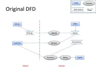
Q1 • No data store in context diagram • 2. Payment- extra dataflow in level-0 • 3. Customer data– from source to data store directly • 4. Order- bidirectional dataflow • 5. Order details & inventory data – wrong forked dataflow (different data) • 6. Process 3.0 – No output
Payment Q2- Context DFD for Textbook Inventory System Payment Payment Payment
Q3 - Student Administration System • Student Administration System : The enrolment process works as follows: • Students send in an application form containing their personal details, and their desired course. The university checks that the course is available and that the student has necessary academic qualifications. If the course is available the student is enrolled in the course, and the university confirms the enrolment by sending a confirmation letter to the student. If the course is unavailable the student is sent a rejection letter.
Q3 - Student Administration System • Context DFD for the Student Administration System • Step 1 • Familiarize yourself with the case study. • Step 2 (identify potential external entities) • Student. • Step 3 (identify flows to/from system and external entities) • Student send: Application details • Student receive: Confirmation/ rejection details
Q3 - Student Administration System • Step 4 (draw your context diagram)
Q3 - Student Administration System • Draw a Level 0 DFD for the Student Administration System . • Steps 1 & 2 (identify potential processes) • Verify availability, Enroll student, Confirm registration. • Step 4 (identify data flows) • Requested-courses, Accepted/rejected selection, registration, confirmation letter, open-course, course-details , course- enrollment, student-details, • Step 5 (identify data stores) • Course file , student file • Step 6 (draw level 0 diagram)
Q3 - Precision Tools System • Precision Tools System: Precision Tools sells a line of high-quality woodworking tools. When customers place orders on the company’s Web site, the system checks to see if the items are in stock, issues a status message to the customer, and generates a shipping order to the warehouse, which fills the order. When the order is shipped, the customer is billed. The system also produces various reports.
Q3 - Precision Tools System • Context DFD for the Precision Tools System • Step 1 • Familiarize yourself with the case study. • Step 2 (identify potential external entities) • Customer, Warehouse, Accounting • Step 3 (identify flows to/from system and external entities) • Customer sends: order, payment • Customer receives: status message , invoice • Warehouse sends: shipping confirmation • Warehouse receives: in stock request, shipping order • Accounting receives : inventory reports
Q3 - Precision Tools System • Step 4 (draw your context diagram)
Q3 - Precision Tools System • Draw a Level 0 DFD for the Precision Tools System • Steps 1 & 2 (identify potential processes) • Check Status ,Issue Status Messages, Generate Shipping Order, Manage Accounts Receivable, Produce Reports • Step 4 (identify data flows) • Order, In-Stock Request, Order Data, Status Data, Status Message, Shipping Order, Order Data, Invoice , Shipping Confirmation, Payment, Accounting Data, Accounts Receivable Data, Order Data, Inventory Reports • Step 5 (identify data stores) • Pending Orders, Accounts Receivable • Step 6 (draw level 0 diagram)