Download
1 / 35
350 likes | 601 Views
03/16/2007. Compiled by Rafael, Ravikanth and Hrishi. Table Of Contents. IntroductionTypes Of DACSpecificationsApplicationsConclusion. 03/16/2007. Compiled by Rafael, Ravikanth and Hrishi. INTRODUCTION. The DAC fundamentally converts finite-precision numbers (usually fixed-point binary numbers)

E N D
1. 03/16/2007 Compiled by Rafael, Ravikanth and Hrishi DIGITAL TO ANALOG CONVERTOR A quick presentation to introduce our peers on the techniques, specifications and applications of the DAC
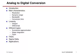
2. 03/16/2007 Compiled by Rafael, Ravikanth and Hrishi Table Of Contents Introduction
Types Of DAC
Specifications
Applications
Conclusion
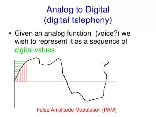
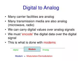
3. 03/16/2007 Compiled by Rafael, Ravikanth and Hrishi INTRODUCTION The DAC fundamentally converts finite-precision numbers (usually fixed-point binary numbers) into a physical quantity, usually an electrical voltage. Normally the output voltage is a linear function of the input number. Usually these numbers are updated at uniform sampling intervals and can be thought of as numbers obtained from a sampling process
4. 03/16/2007 Compiled by Rafael, Ravikanth and Hrishi
5. 03/16/2007 Compiled by Rafael, Ravikanth and Hrishi Output is a sequence of piecewise constant values or rectangular pulses, means that there is an inherent effect of the zero-order hold on the effective frequency response of the DAC resulting in a mild roll-off of gain at the higher frequencies
6. 03/16/2007 Compiled by Rafael, Ravikanth and Hrishi
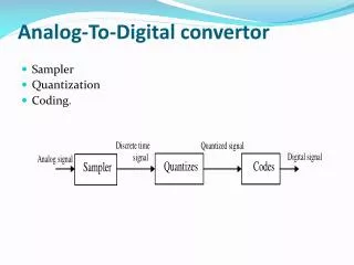
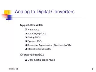
7. 03/16/2007 Compiled by Rafael, Ravikanth and Hrishi Types of DACs Many types of DACs available.
Usually switches, resistors, and op-amps used to implement conversion
Three Types:
Resistor String
Binary Weighted Resistor
R-2R Ladder
PWM (Pulse Width Modulation)
8. 03/16/2007 Compiled by Rafael, Ravikanth and Hrishi
9. 03/16/2007 Compiled by Rafael, Ravikanth and Hrishi
10. 03/16/2007 Compiled by Rafael, Ravikanth and Hrishi SELECTION SWITCHES
11. 03/16/2007 Compiled by Rafael, Ravikanth and Hrishi
12. 03/16/2007 Compiled by Rafael, Ravikanth and Hrishi Advantages:
simple
fast for < 8 bits
Disadvantages:
high element count for higher resolutions, reason:
number of resistors:
number of switches:
slow for > 10 bits
13. 03/16/2007 Compiled by Rafael, Ravikanth and Hrishi Binary Weighted Resistor DAC Utilizes a summing op-amp circuit
Weighted resistors are used to distinguish each bit from the most significant to the least significant
Transistors are used to switch between Vref and ground (bit high or low)
14. 03/16/2007 Compiled by Rafael, Ravikanth and Hrishi Summing OP-Amps Inverting summer circuit used in Binary Weighted Resistor DAC.
V(out) is 180� out of phase from V(in)
15. 03/16/2007 Compiled by Rafael, Ravikanth and Hrishi Binary Weighted Resistor Assume Ideal Op-Amp
No Current into OP-Amp
Virtual ground at inverting input
16. 03/16/2007 Compiled by Rafael, Ravikanth and Hrishi Calculation
17. 03/16/2007 Compiled by Rafael, Ravikanth and Hrishi Cont�d
18. 03/16/2007 Compiled by Rafael, Ravikanth and Hrishi Advantages and Disadvantages Advantages
Easy principle/construction
Fast conversion
Disadvantages
Requirement of several different precise input resistor values: Requires large range of resistors (2048:1 for 12-bit DAC) with necessary high precision for low resistors one unique value per binary input bit. (High bit DACs)
Larger resistors ~ more error.
Precise large resistors � expensive.
19. 03/16/2007 Compiled by Rafael, Ravikanth and Hrishi R-2R ladder DAC Example Convert 0001 to analog
20. 03/16/2007 Compiled by Rafael, Ravikanth and Hrishi R-2R DAC Example (cont.)
21. 03/16/2007 Compiled by Rafael, Ravikanth and Hrishi Conversion Equation
22. 03/16/2007 Compiled by Rafael, Ravikanth and Hrishi Advantages
Only two resistor values
Does not need as precision resistors as Binary weighted DACs
Cheap and Easy to manufacture
Disadvantages
Slower conversion rate
23. 03/16/2007 Compiled by Rafael, Ravikanth and Hrishi Pulse Width Modulation
24. 03/16/2007 Compiled by Rafael, Ravikanth and Hrishi SPECIFICATIONS Resolution
Speed
Linearity
Settling Time
Reference Voltage
Errors
25. 03/16/2007 Compiled by Rafael, Ravikanth and Hrishi RESOLUTION Defined by the change in output voltage for a change of the LSB.
Related to the size of the binary representation of the voltage. (8-bit)
Higher resolution results in smaller steps between voltage values
26. 03/16/2007 Compiled by Rafael, Ravikanth and Hrishi SPEED
Defined by the rate at which the register value is updated.
Also called the conversion rate or sampling rate
Speed is limited by the clock speed of the microcontroller and the settling time of the DAC
27. 03/16/2007 Compiled by Rafael, Ravikanth and Hrishi LINEARITY Represents the relationship between digital values and analog outputs
Should be related by a single proportionality constant. (constant slope)
28. 03/16/2007 Compiled by Rafael, Ravikanth and Hrishi SETTLING TIME Time in which the DAC output settles at the desired value � � VLSB.
Ideally, an instantaneous change in analog volatage would occur when a new binary word enters into the DAC
29. 03/16/2007 Compiled by Rafael, Ravikanth and Hrishi REFERENCE VOLTAGE Used to determine how each digital input will be assigned to each voltage division
Types:
Non Multiplier DAC: Vref is fixed
Multiplier DAC: Vref provided by external source
30. 03/16/2007 Compiled by Rafael, Ravikanth and Hrishi ERRORS Gain
Offset
Full scale
Non-Monocity
31. 03/16/2007 Compiled by Rafael, Ravikanth and Hrishi GAIN ERROR Occurs when the slope of the actual output deviates from the ideal output
32. 03/16/2007 Compiled by Rafael, Ravikanth and Hrishi OFFSET ERROR Occurs when there is a constant offset between the actual output and the ideal output
33. 03/16/2007 Compiled by Rafael, Ravikanth and Hrishi FULL SCALE ERROR Occurs when the actual signal has both gain and offset errors
34. 03/16/2007 Compiled by Rafael, Ravikanth and Hrishi Non-Monotonic Error Occurs when an increase in digital input results in a decrease in the analog output
35. 03/16/2007 Compiled by Rafael, Ravikanth and Hrishi Common Applications Electronic Cruise Control
Computer Printers
Sound Equipment (e.g. CD/MP3 Players)
Project applications
Motor speed controller
Solenoid valves (pneumatics)