Download
1 / 33
330 likes | 510 Views
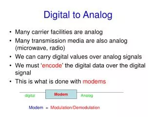
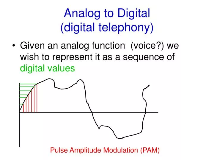
Analog to Digital (digital telephony). Given an analog function (voice?) we wish to represent it as a sequence of digital values. Pulse Amplitude Modulation (PAM). Pulse Code Modulation ( PCM ). Pulse Code Modulation is a variation of PAM

E N D
Analog to Digital(digital telephony) • Given an analog function (voice?) we wish to represent it as a sequence of digital values Pulse Amplitude Modulation (PAM)
Pulse Code Modulation (PCM) • Pulse Code Modulation is a variation of PAM Measurements are changed to a set of integral values • How often should the analog signal be sampled? • A result of Nyquist’s Theorem says For a signal with frequency x Maximum sampling rate = 2 * x • For a voice channel Max frequency of voice channel = 4000 Hz Maximum sampling rate needed = 2 * 4000 = 8000 samples per second
Pulse Code Modulation • Establish a set of integral values Plus/minus 7 bits Total of 8 bits per sample Total of 256 distinct values • This is how voice is encoded as a digital signal • Sample 2 * 4000 = 8000 samples per second • One sample every125 microseconds
Pulse Code Modulation These samples are pooled into groups of 24 VOICE 64 Kbps Codec 8000 samples/sec 1 Codec Frame 2 24 8 bits 8 bits 8 bits 8 bits 8 bits F 8 * 24 = 192 bits 1 frame bit
Pulse Code Modulation (PCM) • 24 channels • Each frame is 193 bits • Sampled 8000 times per second 193 bits * 8000 samples = 1,544,000 bits per second • This is called a T1 facility • The circuit is also called a Digital Service-1 (DS-1) • This is the fundamental digital circuit from the telephone company • A single channel within the DS-1 is often called a DS-0 • There is a European standard that groups 30 channels instead of 24 – Called an E1 circuit
Digital Service • Uses Alternate Mark Inversionor AMI encoding • Requires all one bits to be alternating positive and negative voltages • Zero bits have 0 voltage 0 1 1 1 0 0 0 1
Multiplexing • To more fully utilize channel capacity more than one transmission can ‘share’ a single channel • The is called multiplexing • Multiplexing can take many forms Frequency Division The total bandwidth is divided a number into a number of frequency ranges Each transmission utilizes one of these ranges
Cable Television • A single coax cable system can have a total capacity of 350 Mhz and to over 650 Mhz • Each TV channel occupies 6 Mhz Channel Band Number Mhz 2 54-60 3 60-66 4 66-72 …… ………. 20 156-162 ……. ………. 40 318-324 ……. ……….. 61 444-450
Wave Division Multiplexing • Using multiple ‘colors’ over fiber optical cable is a form of frequency division • Multiple transmission can exist concurrently over the same fiber cable • Each uses a different wave length, typically called a ‘lamda’
Time Division Multiplexing • Total bandwidth is divided into a series of ‘n’ time slots • Each transmission gets one of the time slots in a round robin fashion T1 T1 T2 T2 T3 T4 T3 T2 T1 T4 T2 T1 T3 T3 Communications Channel T4 T4
Statistical Multiplexing • Like time division except when a station does not have data to send, slot is passed on to next transmission • Could have variable length data for each transmission • Any one link can actually get use of full link of other are idle • Better link utilization • More overhead
Statistical Multiplexing T1 T1 T2 T2 T1ddT3ddT1d T4dddT3ddT1d T3 T3 Communications Channel T4 T4
Inverse Multiplexing • A number of slower speed lines are grouped together to form a higher speed circuit M U X M U X Multiplexing M U X M U X Inverse multiplexing
Recall PCM • Establish a set of integral values Plus/minus 7 bits Total of 8 bits per sample Total of 256 distinct values • This is how voice is encoded as a digital signal • Sample 2 * 4000 = 8000 samples per second • One sample every125 microseconds
Pulse Code Modulation These samples are pooled into groups of 24 VOICE 64 Kbps Codec 8000 samples/sec 1 Codec Frame 2 24 8 bits 8 bits 8 bits 8 bits 8 bits F 8 * 24 = 192 bits 1 frame bit
Digital Hierarchy Phone Company pools T1s into larger circuits 1.544 mbps DS-2 6.312 Mbps 24 DS-0 64 kbps DS – 3 44.736 Mbps DS-4 4 DS-1 274.176 7 DS-2 6 DS-3
Synchronous Optical NetworkSONET • Standard for digital transmission over fiber optics • Also called Synchronous Digital Hierarchy (SDH) by the ITU • Provides for interoperability between carriers • Standardizes US and European hierarchy • Extends Digital Hierarchy beyond existing DS-3 and DS-4 • Makes provision for Operations, Administration, and Maintenance
SONET • Synchronous • Basic frame 810 bytes 8,000 frames per second 6480 bits per frame or 51.84 Mbps • This forms a basic SONET channel 6480 6480 6480 6480 Synchronous Transport Signal -1 STS-1
Integrated Services Digital NetworkISDN • Designed to provide digital services to end users (total telephone redesign) • Approved in 1984 (ISO, ITU) • All digital services all the way to the home • Uses same twisted pair cabling • Initially slow implementation • Usually priced as a measured service, even for local calling • Very limited user acceptance
ISDN Services • Basic Rate Interface (BRI) 2 B (basic rate) channels each 64 Kbps used for voice, concurrent data 1 D channel 16 Kbps, used for signaling • Primary Rate Interface (PRI) 23 B channels 1 D channel (at 64 Kbps)
Digital Subscriber Line (DSL) • Effort by telephone company to bring lower cost, high speed service to home • Provides concurrent voice/data • Uses regular phone twisted pair • Intended to compete with cable service • Multitude of variations • Speeds from several hundred Kbps to several Mbps
DSL Variants • Asymmetric DSL • Frequency division multiplexing • 0 – 25 Khz Voice • 25 – 200 Khz Upstream data • 250 – 1000 Khz Downstream data • Rates up to 1 Mbps upstream 8 Mbps Downstream are theoretically possible
Digital Subscriber Lines Operation of ADSL using discrete multitone modulation (DMT). Upstream: Usually 512 Kbps or less Downstream: Up to 8 Mbps
Digital Subscriber Lines Bandwidth versus distanced over category 3 UTP for DSL.
Other DSL Variants • Symmetric DSL (SDSL) • Upstream and downstream speeds the same • Single copper pair • High Data Rate DSL (HDSL) • Symmetric services • Requires two copper pairs • Cost effective way to deliver T1 equivalent service • Very High Data Rate (VDSL) • Asymmetric • Up to 50 Mbps downstream possible
DSL Modem Digital Subscriber Line Access Multiplexor
Cable Modems • Why cable? • Infrastructure exists • Coax cable better characteristics than twisted pairs • TV channels are 6 Mhz • Allows for high speed data • What is maximum possible data rate? • Shared channel – many users on a segment • Now a standard Data Over Cable System Interface Standard DOCSIS
Cable Spectrum Allocation Frequency allocation in a typical cable TV system used for data
Cable modems • Upstream: 5-42 Mhz • Uses an encoding scheme of 2 bits per baud • 1 baud per Hz • 12 Mbps per channel possible per 6 Mhz channel • Downstream: 550-750 Mhz • Uses 64-QAM • 6 bits/baud, 1 bit is used for error correction • Theoretical 30 Mbps per 6 Mhz channel
Wireless Broadband Alternatives • Current efforts are to provide 802.11 wireless in large areas through meshed access points • Wireless broadband to the home standard being developed • IEEE 802.16 - WiMAX • Potential of upto155 Mbps • Over wide areas (miles) • Considered a replacement for last mile http://grouper.ieee.org/groups/802/16/index.html