Download
1 / 7
70 likes | 75 Views
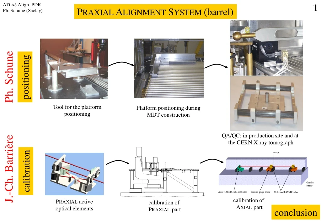
The PRAXIAL alignment system ensures precise positioning of the platform during MDT construction. It includes tools for platform positioning and calibration, as well as QA/QC measures during production and testing. The system helps control mechanical deformation and verifies the final platform position relative to MDT wires.

E N D
ATLAS Align. PDR Ph. Schune (Saclay) 1 PRAXIAL ALIGNMENT SYSTEM (barrel) Ph. Schune positioning Tool for the platform positioning Platform positioning during MDT construction QA/QC: in production site and at the CERN X-ray tomograph J.-Ch. Barrière calibration calibration of AXIAL part PRAXIAL active optical elements calibration of PRAXIAL part conclusion
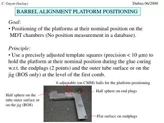
ATLAS Align. PDR Ph. Schune (Saclay) 2 Y Z X Atlas axis PRAXIAL ALIGNMENT SYSTEM Tool for the platform positioning • Principle: • The PRAXIAL system is used to unite a layer of chambers (about 6 MDT) • to form a single “rigid” layer. It is composed by two systems. • The precision on the positioning of both systems are: • ±25 mm (y,z), ±200 mm (x), < 80 mrad (x,z), ±200 mrad (y). • Goal(for the positioning): • Positioning of the (four) platforms at their nominal position on theMDTchambers (no position measurement in a database). The calibration of the active optical elements is done elsewhere • Method: • Use four precisely adjusted template squares (precision < 20 mm) to • hold the platform at theirnominal position, during the glue curing, • w.r.t. the end plugs (2 pts)and the outer tube surface(or on thejig, BOS only) at the level of thefirstcomb. • J.-Ch.B., C.G. and H.v.d.G. presentations PRAXIAL Platform Template squares calibration (CMM) red = proj. blue = praxial green= ref. 3D view.
ATLAS Align. PDR Ph. Schune (Saclay) 3 PRAXIAL ALIGNMENT SYSTEM Platform positioning during MDT construction 6 adjustable (on CMM) balls for the platform positioning (s < 20 mm) Half sphere on the MDT tube outer surface (oron the jig, BOS) Half sphere on MDT end plugs Flat surface on MDT end plugs The platform is glued at its nominal position during the glue curing of the first MDT layer. Template square template square with its precise positioning sphere glue PRAXIAL platform Gluing of the platform (detail) end-plug of the tube (circularity: s < 20 mm) jig
ATLAS Align. PDR Ph. Schune (Saclay) 4 mrad CCD LEDs marble table PRAXIAL ALIGNMENT SYSTEM QA/QC: in production site and at the CERN X-ray tomograph Goal: Control the chamber mechanical deformation (sag angular displacement of the platform) coming from the assembly of the different layer (e.g. BIS-Thessaloniki). Method: Use four control tower (one on each platform) each equipped with 4 LED and 2 CCD ( two crossed BCAM). The towers calibrate (relative) platform position: qx, qy and qz. Special software distributed to all labs. • J.B. Control tower in position Rotation angle vs step (BIS-0): sag. of the chamber Platform angle ~ (X/Y(pixel) - X0/Y0) * pixel_size / f CCD image of the 2 LED from the opposite tower: s ~ 0.5 pixel < 100 mrad Calibration bench of the tools (in each lab., if possible) distance adjusted to ± 2 mm
ATLAS Align. PDR Ph. Schune (Saclay) 5 microscope Y spheres for the positioning 4 W/Au wires (Ø = 100 mm) Z support only needed during the calibration X 2D table PRAXIAL ALIGNMENT SYSTEM QA/QC: in production site and at the CERN X-ray tomograph Goal: Verify the final platform position w.r.t. to MDT wires. Method: Use four masks (one on each platform) equipped with wires. The masks wires are precisely located w.r.t. to the positioning spheres (< 10 mm). Four X-ray tomo scans ( ) are needed for measuring the platforms position. These masks calibrate absolute platforms position: qx, qy, qz and Dy, Dz. MASK 1 MASK 3 HV side RO side BML chamber MASK 2 MASK 6 Chamber on tomograph (top view) Mask with its 4 wires • After the calibration (“optical CMM”) of • the four masks, we know the wires and • spheres position with the following precision: • wires (4): • = 100 mm 2 mm • straightness < 5 mm • positioning spheres (6): • = 8 mm 5 mm Optical CMM
ATLAS Align. PDR Ph. Schune (Saclay) 6 PRAXIAL ALIGNMENT SYSTEM QA/QC with the X-ray tomograph (with BML-0) • Difficulty in interpreting X-tomo results but more generally difficulty of the alignment: • muons are measured using the wires but alignment elements are positioned on the tubes. • we have to understand the tube sag w.r.t. wire sag with a precision < 30 mm in all conditions: position in the exp., flexo, T gradient… (see ATLAS-TDR) Z top view B M L X Atlas axis exchange of masks position 1) Lab. conditions: (marble table, T=cte) Y of the mask wires w.r.t. the platform: < > ~ 5 mm s < 11 mm marble table Y 2) CERN X-tomo or ATLAS conditions: -40 0 40 (mm) Z of the mask wires w.r.t. the platform: < > < 1 mm s < 6 mm platform X-tomo results (sag. compensation up to 600 mm): Ysag. comp.-Yno sag. comp ~ 40 mm -10 0 10 (mm) These measurements include errors from: repositioning, X-tomo measurement error and uncertainty from local frame tube
ATLAS Align. PDR Ph. Schune (Saclay) 7 PRAXIAL ALIGNMENT SYSTEM Positioning precision Positioning Positioning tool (CMM): s < 20 mm End-plug circularity: s < 20 mm Platform quality +repeatability of the positioning: s ~ 10 mm (special tools will be designed/made to help for the positioning) Control Mask for X-tomo (absolute): strans.< 10 mm and srot.< 100 mrad (first complete measurement: BML-1, April 2001) Control tower (relative angular movement): s < 100 mrad optical sensor calibration J.-Ch. B. presentation