Download
1 / 7
70 likes | 194 Views
World Journal of Nano Science and Engineering http://www.scirp.org/journal/wjnse Paper ID: 4400054 Support Information: SI-1 Energy staggered interface: electrical charge separation mechanism. Title Interface recombination & emission applied to explain photosynthetic mechanisms for

E N D
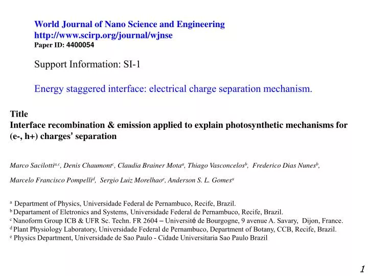
World Journal of Nano Science and Engineering http://www.scirp.org/journal/wjnse Paper ID: 4400054 Support Information: SI-1 Energy staggered interface: electrical charge separation mechanism. Title Interface recombination & emission applied to explain photosynthetic mechanisms for (e-, h+) charges’ separation Marco Sacilottia,c, Denis Chaumontc, Claudia Brainer Motaa, Thiago Vasconcelosb, Frederico Dias Nunesb, Marcelo Francisco Pompellid, Sergio Luiz Morelhaoe, Anderson S. L. Gomesa a Department of Physics, Universidade Federal de Pernambuco, Recife, Brazil. b Departament of Eletronics and Systems, Universidade Federal de Pernambuco, Recife, Brazil. c Nanoform Group ICB & UFR Sc. Techn. FR 2604 – Université de Bourgogne, 9 avenue A. Savary, Dijon, France. d Plant Physiology Laboratory, Universidade Federal de Pernambuco, Department of Botany, CCB, Recife, Brazil. e Physics Department, Universidade de Sao Paulo - Cidade Universitaria Sao Paulo Brazil 1
Energy band bending. Electric field = - grad V Force = E x charge energy = V x charge interface - CB CB EFB Material A Material B EFA VB VB Note that quasi-Fermi level EFA should go down, CB & VB go up for A. + Note that quasi-Fermi level EFB should go up, CB & VB go down for B. Figure SI-1-1, representing the energy staggered interface: electrical charge separation mechanism. How does the energy band bending arrive at the energetic interface? The flow of charges from one material to the nearby material creates an electronic no-equilibrium on both materials, near the interface. This electronic non-equilibrium creates potential variation. It creates the necessary electric field to separate charges: e- from h+. 2
Figure SI-1-2, representing the energy staggered interface. It represents the charge separation mechanism in a picturial slow motion maner. Excitation of such an energetic structure with only 4 photons. interface Cathode - - - - - - - - - BC - - - - - - - - - - - - - BC - Material A Anode - hvi hvi hvi Material B + BV + + + + + + + + + + + + + + + BV + + + + + + + + Energy balance: 4 hv photons as excitation 3 hvi photons emission at interface 1 (e-, h+) separated ( 25% efficiency) hvi is related to the spent energy to separate (e-, h+). Note: photosynthesis is about 5% final efficiency. 2hv 2hv 3
Figure SI-1- 3, representing the energy staggered interface: charge separation mechanism applied to photosynthetic first step processes. Note the hudge electric field crossing the interface for the AlInAs/InP system (see text). For organic molecules, this electric field should be much higher since the excitonic attraction is much higher than for inorganic materials. - - + - + + CO2 + H2O sucrose Eband-bending≈105 V/cm water O2 Interface electric field crossing the interface interface Cathode BC Anode BC - hvi Material A Material B BV + BV 4
Why is the interface emission peak so large? See it in the nexts slides… 5
interface Material B Material A Quasi-triangular shape quantum well for e-. <-- electrons Qe S hvi = S + Qe + Qh - Ex _ + h absorption is possible Energy levels to be filled up with h+, upon light excitation. Ex= interaction Qh holes --> Figure SI-1-4, representing the interface physical parts linked to the interface emission peak. All the terms of the equation below should change with the excitation intensity. Mainly ∆Qe + ∆Qh should change more than the others terms. This explain why the interface PL & EL emission peaks’ are so large. 6 Note: no quantum mechanics selection rules, for e- & h+ recombination at the interface
Figure SI-1-5, representing the interface physical parts linked to the interface recombination/emission peak. The interface recombination and emission depends on the e- & h+ wavefunctions’ interface overlap. The 1 to 2 nm wavefunction penetration is for the AlInAs/InP system (see text). Material B Material A Permanent e- population inversion (µe- > µh+) <-- electrons + ~ 2 nm - S emission & absorption hv Is there any meaning to talk about lifetime measurements for all these hazardous energy levels (e-, h+) recombination? ~1 nm holes --> interface e- wavefunction h+ wavefunction No quantum mechanics selection rules for recombination; because e- & h+ are seated on different materials. 7