Download
1 / 14
140 likes | 310 Views
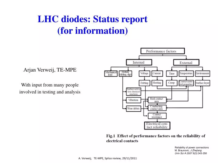
LHC diodes: Status report (for information). Arjan Verweij, TE-MPE With input from many people involved in testing and analysis. Reliability of power connections M. Braunovic , J Zhejiang Univ Sci A 2007 8(3):343-356. A. Verweij, TE-MPE, Splice review, 29/11/2011.

E N D
LHC diodes: Status report (for information) Arjan Verweij, TE-MPE With input from many people involved in testing and analysis Reliability of power connections M. Braunovic, J Zhejiang UnivSci A 2007 8(3):343-356 A. Verweij, TE-MPE, Splice review, 29/11/2011
The diode (incl. heat sinks and diode leads) is the bypass in case a magnet quenches. • Similarly to the bus, the diode has to carry 12 kA, t=100 s (RB) or t=30 s (RQ). • Any high resistive singularities (e.g. contact resistances) can cause local overheating. • Rupture of a diode lead can result in local dissipation of up to 1 GJ !!! • The LHC contains 1232 dipole diode stacks and 392 quadrupole diode stacks. A. Verweij, TE-MPE, Splice review, 29/11/2011
The dipole diode stack Rbus-bus (aka ‘half moon’) Lower diode busbar Diode box, Helium contents : 5 liter Upper heat sink RHS-bus Voltage taps on the diode Rdiode-HS Lower heat sink A. Verweij, TE-MPE, Splice review, 29/11/2011
The quadrupolediode stack Lower diode busbar Upper diode busbar Diode 2 Diode 1 RHS-bus Ansys model from S. Izquierdo Rdiode-HS Rbus-bus A. Verweij, TE-MPE, Splice review, 29/11/2011
The diode lead resistance is the sum of: The electro-thermal behavior of the copper leads and heat sinks is well understood, and they are sufficiently over-dimensioned. Contacts are often a source of problem because deterioration of the contact resistance can occur due to oxidation, movement, local heating, etc. A. Verweij, TE-MPE, Splice review, 29/11/2011
The bolted contacts in the diode leads have been discussed many many times in the EEWG in the years 2003-2006, especially the “half moon” contact. (see: http://lhcp.web.cern.ch/lhcp/tcc/powering/eewg/eewg.htm). The minutes of 18/9/2003 state: “…the baseline design leaves the possibility for potential dangers.” An agreement was set during reception to target Rdiode-lead<15 mW, in order to make sure that Thalf-moons<340 K and Twafer<300 K. About 250 diodes have been repaired at CERN, since they had Rbus-bus and RHS-bus up to a few 100 mW. After the repair all resistances were below 5 mW, according to measurements at warm (up to 10 A) and at cold (up to about 1000 A). During 4 technical stops in 2011 the resistances of the leads of 6 dipole diodes and 6 quadrupole diodes in S56 were measured after heater induced quenches in the magnets. A. Verweij, TE-MPE, Splice review, 29/11/2011
Results for the dipole diode lead ‘resistances’ for 2 kA quenches Constant resistance of the diode leads Redistribution of current from diode into magnet A. Verweij, TE-MPE, Splice review, 29/11/2011
Results for the dipole diode lead ‘resistances’ for 6 kA quenches The results showed non-reproducible resistances much larger than 5 mW. The graphs could not be explained by ‘normal’ Joule heating in the resistive busbarsincluding constant contact resistances. 1.8-3.6 mW: measured at cold reception in SM18 A. Verweij, TE-MPE, Splice review, 29/11/2011
Similar results were seen on the quad diodes All resistances in mW A. Verweij, TE-MPE, 15/11/2011 A. Verweij, TE-MPE, Splice review, 29/11/2011
D16R5 anode: 2 consecutive quenches at 5 kA Step in Dt<50 ms Probably a movement in one of the bolted connections during the first tests, resulting in a permanent increase in the contact resistance. A. Verweij, TE-MPE, Splice review, 29/11/2011
The diode lead resistances measured in the machineare much larger than expected, are non-reproducible, and show degradation at 3 kA. The resistance strongly depends on the ‘quench’ current and on the current and/or Idt during previous tests. Different behaviors are observed so different physical/mechanical phenomena may play a role. The origin of the large resistance is not known, and extrapolation 12 kA is not possible. In order to better understand the observed behavior, an informal working group was created in Aug 2011. Main activities are: • Mechanical measurements and calculations (Ansys). • Electro-thermal simulations (Comsol). • Data collecting from the series production (ENEA) and reception • tests at SM18 and Block 4. • Resistance measurements at 80/300 K under loading (up to 6 kA). • Diode measurements at cold in SM18 (up to 13 kA). • Microscopic analysis of contact surfaces. Members FrédéricSavary Luca Bottura Andrzej Siemko Knud Dahlerup-Petersen Marta Bajko Gaelle Dib Christian Giloux Herve Prin Susana IzquierdoBermudes Philippe Perret Gerard Willering Elvis Fornasiere Mateusz JakubBednarek Giorgio D'Angelo Michael Guinchard Ludovic Grand-Clement Arjan Verweij The progress on these activities was presented during a small workshop on 15 Nov with already a lot of very interesting data/results. A. Verweij, TE-MPE, Splice review, 29/11/2011
Block-4 measurements show high resistances during the first runs, saturating to low values during the 13 kA runs. But how would the curve look like if the 1st quench would be at 13 kA?? A. Verweij, TE-MPE, Splice review, 29/11/2011
During the Frascati tests different behaviors were observed, see the example. The diode to heat-sink resistance might decrease or increase with the number of runs. Usually the resistance reduces during the decay of the current! A. Verweij, TE-MPE, Splice review, 29/11/2011
Conclusion • The behavior in the machine was unexpected, but analysis of data from the past shows that a similar behavior was already present during reception tests. • There is a strong indication that most of the resistance is at the “diode - heat sink” contact. • The heat sink has a lot of margin, and a large Rdiode-HS is acceptable as long as there is sufficient thermal contact between diode and heat sink. • Opening of the circuit in case of overheating of the diode or the contact between diode and heat sink is unlikely due to the presence of the 40 kN force. • The bolted contacts should also be carefully looked at, even though opening of a properly bolted contact (with washers) is not very likely. • Restarting the diode tests at CERN (in SM18) with more instrumentation will surely give more insight in the behavior of the contacts. • During the dipole training campaign in S56 in 2008 no problems have been observed in the functioning of the diodes. A. Verweij, TE-MPE, Splice review, 29/11/2011