Download
1 / 5
50 likes | 191 Views
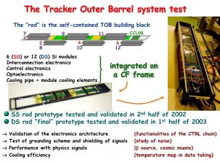
MIMOSA9 tracker test chip submission. Goals: design optimization for STAR microvertex application 1. Exploration of (new) fabrication process 2. Test of a new readout architecture Status: submitted 26 of January 04 expected in April 04 tests (including beam tests) in May-July 04.

E N D
MIMOSA9 tracker test chip submission Goals: design optimization for STAR microvertex application1. Exploration of (new) fabrication process2. Test of a new readout architectureStatus: submitted 26 of January 04 expected in April 04 tests (including beam tests) in May-July 04
AMS 0.35 µm CMOS OPTO process • Advanced mixed-signal polycide gate CMOS: 4 metal, 2 poly, high-resistive poly, 3.3V and 5V gates- Optimized N-well diode leakage current:<45 pA/mm2 (cm2???) @27 °C- 20 µm epi substrate(samples on non-epi high resistivity substrate also available)- Availability in multiproject submissions in 2004, with a reasonable pricing
MIMOSA9: 4 “standard” arrays for tracking performance study and 5 test arrays with a new readout scheme (analog CDS on pixel) Test arrays (on pixel CDS) Dimensions: 4.1x4.3 mm2 Array#1 Array#2 Array#0 Array#3
Mimosa9: arrays for tracking study vdd vdd reset select output 3 transistor pixel cell gnd vdd * “thin oxide diode” vdd select POLY M1 plate output N++ N++ P++ LOCOS N-WELL P-WELL Self-biased pixel cell gnd
Analog CDS on pixel: possible way to limit the integration time, effective use of a trigger) - Slow integration clock (1MHz 640 µs integration time): low dissipation, comfortable stabilisation time of the on-pixel amplifier after Power_On - Readout of all pixels after trigger only: no need for perfect internal readout chain compensation - External compensation, global correction (common mode) possible: limited risk for experimental “unknown” factors - Lower signal amplitude dispersion: less power, smaller digitisation precision required (~8bits) S1 vbias AVDD Read1 pwr_on output1 Cs1 S2 AVDD x(5-10) Read2 output2 Cs2 gnd output1 Out BUF output2 Five different pixel arrays tested on Mimosa9 (array size 22x4 pixels for a pitch of 30µm)