Download
1 / 22
240 likes | 611 Views
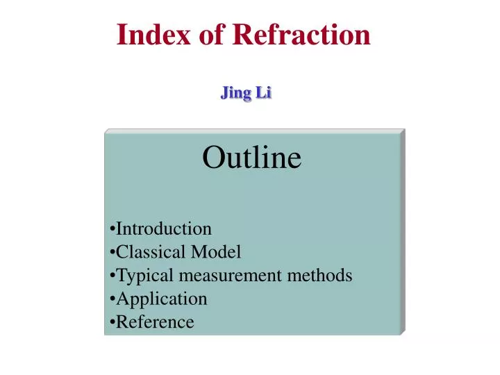
Index of Refraction. Jing Li. Outline Introduction Classical Model Typical measurement methods Application Reference. Definition of Index of Refraction. In uniform isotropic linear media, the wave equation is:. They are satisfied by plane wave y =A e i( k r- w t)

E N D
Index of Refraction Jing Li • Outline • Introduction • Classical Model • Typical measurement methods • Application • Reference
Definition of Index of Refraction In uniform isotropic linear media, the wave equation is: They are satisfied by plane wave y=A e i(k r-wt) y can be any Cartesian components of E and H The phase velocity of plane wave travels in the direction of k is
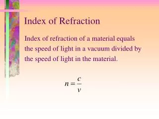
Definition of Index of Refraction We can define the index of refraction as Most media are nonmagnetic and have a magnetic permeability m=m0, in this case In most media, n is a function of frequency.
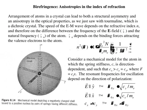
Classical Electron Model ( Lorentz Model) w0 E + X - Let the electric field of optical wave in an atom be E=E0e-iwt the electron obeys the following equation of motion X is the position of the electron relative to the atom m is the mass of the electron w0 is the resonant frequency of the electron motion g is the damping coefficient
Classical Electron Model ( Lorentz Model) The solution is The induced dipole moment is a isatomic polarizability The dielectric constant of a medium depends on the manner in which the atoms are assembled. Let N be the number of atoms per unit volume. Then the polarization can be written approximately as P = N p = N aE = e0 c E
Classical Electron Model ( Lorentz Model) The dielectric constant of the medium is given by e = e0 (1+c) = e0 (1+Na/ e0) If the medium is nonmagnetic, the index of refraction is n= (e /e0)1/2 = (1+Na/ e0 )1/2 If the second term is small enough then
Classical Electron Model ( Lorentz Model) The complex refractive index is at w ~w0 , Normalized plot of n-1 and k versus w-w0
For more than one resonance frequencies for each atom, Classical Electron Model ( Drude model) If we set w0=0, the Lorentz model become Drude model. This model can be used in free electron metals
Relation Between Dielectric Constant and Refractive Index By definition, We can easily get:
An Example to Calculate Optical Constants Real and imaginary part of the index of refraction of GaN vs. energy;
Kramers-Kronig Relation The real part and imaginary part of the complex dielectric function e (w) are not independent. they can connected by Kramers-Kronig relations: P indicates that the integral is a principal value integral. K-K relation can also be written in other form, like
A Method Based on Reflection Typical experimental setup ( 1) halogen lamp; (2) mono-chromator; (3) chopper; (4) filter; (5) polarizer (get p-polarized light); (6) hole diaphragm; (7) sample on rotating support (q); (8) PbS detector(2q)
Calculation z E1' n2=nr+i n i n1=1 q x q E1 In this case, n1=1, and n2=nr+i n i Snell Law become: Reflection coefficient: Reflectance: R(q1, l, nr, n i)=|r p|2 From this measurement, they got R, qfor each wavelength l, Fitting the experimental curve, they can get nr and n i . Reflection of p-polarized light
Results Based on Reflection Measurement Single effective oscillator model (Eq. 1) (Eq. 2) FIG. 2. Measured refractive indices at 300 K vs. photon energy of AlSb and AlxGa1-xAsySb1-y layers lattice matched to GaSb (y~0.085 x). Dashed lines: calculated curves from Eq. ( 1); Dotted lines: calculated curves from Eq. (2) E0: oscillator energy Ed: dispersion energy EG: lowest direct band gap energy
Use AFM to Determine the Refractive Index Profiles of Optical Fibers n2 n1 2a The basic configuration of optical fiber consists of a hair like, cylindrical, dielectric region (core) surrounded by a concentric layer of somewhat lower refractive index( cladding). • Fiber samples were • Cleaved and mounted in holder • Etched with 5% HF solution • Measured with AFM There is no way for AFM to measure refractive index directly. People found fiber material with different refractive index have different etch rate in special solution.
AFM • The optical lever operates by reflecting a laser beam off the cantilever. Angular deflection of the cantilever causes a twofold larger angular deflection of the laser beam. • The reflected laser beam strikes a position-sensitive photodetector consisting of two side-by-side photodiodes. • The difference between the two photodiode signals indicates the position of the laser spot on the detector and thus the angular deflection of the cantilever. • Because the cantilever-to-detector distance generally measures thousands of times the length of the cantilever, the optical lever greatly magnifies motions of the tip.
A Method Based on Transmission r1 r2 r3 q n d d q1 t1 t2 t3 • For q=0, input wave function a e if , • tm=aTT’R’2m-1 e i(f-(2m-1)d ) (m=1,2…) • d=2pdn/l • The transmission wave • function is superposed by all tm • a T =a T T’ e ifS m(R’2m-1 e-i(2m-1)d) • =(1-R2)a e i(f-d) /(1-R2e-i2d) • (TT’=1-R2 ; R’=-R) • If R<<1, then • a T =a e i(f-d) • maximum condition is 2d=2pm= 4pdn/l • n(lm)=m lm/2d
Application In our lab., we have a simple system to measure the thickness of epitaxial GaN layer.
Thickness Measurement n(lm)=m lm/2d • Steps to calculate thickness • Get peak position lm • d=(lm lm-1)/2/[lm-1 n(lm) - lmn(lm-1)] • Average d • get m min= n(l max)*2d/ l max • Calculate d : d=m lm/2/n(lm) (from m min for each peak) • Average d again Limit Minimum thickness:~500/n Error<l/2n
Reference • Pochi Yeh, "Optical Wave in Layered Media", 1988, John Wiley & Sons Inc • E. E. Kriezis, D. P. Chrissoulidis & A. G. Papafiannakis, Electromagnetics and Optics, 1992, World Scientific Publishing Co., • Aleksandra B. Djurisic and E. H. Li, J. OF Appl. Phys., 85 (1999) 2848 (mode for GaN) • C. Alibert, M. Skouri, A. Joullie, M. Benounab andS. Sadiq , J. Appl. Phys., 69(1991)3208 (Reflection) • Kun Liu, J. H. Chu, and D. Y. Tang, J. Appl. Phys. 75 (1994)4176 (KK relation) • G. Yu, G. Wang, H. Ishikawa, M. Umeno, T. Soga, T. Egawa, J. Watanabe, and T. Jimbo, Appl. Phys. Lett. 70 (1997) 3209 • Jagat, http://www.phys.ksu.edu/~jagat/afm.ppt (AFM)