Download
1 / 43
430 likes | 620 Views
Explore the birefringent nature of calcite and dichroic crystals, their origins in mineral formation, and optical properties in light transmission. Learn about calcite's abundance in Earth's crust and its role in making linear polarizers.

E N D
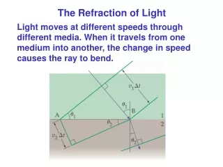
Birefringence: Anisotropies in the index of refraction Arrangement of atoms in a crystal can lead to both a structural asymmetry and an anisotropy in the optical properties, as we just saw with tourmaline, which is a dichroic crystal. The speed of the E-M wave depends on the refractive index n, and therefore on the difference between the frequency of the E-field () and the natural frequency (o) of the atom. o depends on the binding forces attracting the valence electrons to the atom. Consider a mechanical model for the atom in which the spring stiffness, c, is direction-dependent, and such that cx > cy = cz, where F = cix. The resonant frequencies for oscillation depend on the direction of polarization:
Light with frequency d will appear in the absorption band for the polarization in case (a) and will be transparent for the polarization of case (b). This is an example of a dichroic crystal which will allow transmission of light with (b) while strongly absorbing light with at d (a). As a result of the anisotropy in o, the refractive index will depend on the polarization direction. (a) (b) The birefringent case is for = b in which absorption is negligible for both polarizations, but the index of refraction depends on the polarization.
In the simple mechanical model, the spring stiffness is such that cx > cy = cz and thus the x-axis is the direction of the optic axis. x Optic axis Optic axis E z y Plane optic axis Notice that for polarizations with E in a plane normal to the optic axis, the index of refraction n is independent of the polarization orientation. Also nyz > nx. Let’s consider now calcite (calcium carbonate) CaCO3 which is an important birefringent material. It is also the most common material for making linear polarizers for high power lasers.
Calcite is the third most common mineral in Earth’s crust (behind feldspar and quartz). Because of its abundance, calcite can be found in many rock types. A Calcite in Sedimentary Rocks The sedimentary rock limestone makes up approximately 10 percent of all sedimentary rock. Limestone consists almost entirely of calcite. It forms because many marine organisms make shells and other hard body parts out of calcium carbonate. When the organisms die, their shells or hard body parts settle to the ocean floor. Through time, they can accumulate into great thicknesses of calcite mud. This mud, if turned into rock, becomes limestone. Chalk, a form of limestone, consists of the calcium carbonate remains of innumerable microscopic floating marine organisms, such as foraminifera and coccolithophores. From MSN Encarta NaCl Sodium Chloride fcc – Face-centered Cubic Calcite or Calcium carbonate (CaCO3) --- Rhombohedral unit cell Unit Cell
Calcite or Calcium carbonate (CaCO3) 3-fold symmetry CO3 carbonate groups are all in planes normal to the Optic axis. Large Birefringence
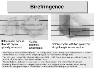
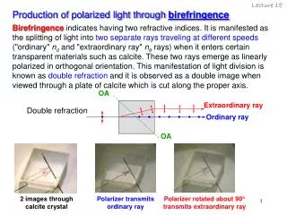
The birefringent property of calcite leads to the formation of two images as shown in these examples. The images are related to the existence of ordinary rays (o-rays) and extraordinary rays (e-rays). An analysis of these rays shows that both these rays are linearly polarized. We will describe the nature of these rays in detail in the coming slides. Colorless Calcite Rhombohedron with a long edge of ~12 cm.
It is possible to cleave calcite and form sharp faces that create a cleavage form (rhombohedron) as shown below possessing faces of a parallelogram with angles of 78.08 and 101.92. There are only two blunt (not sharp) corners (labeled A and B) where the surface planes meet. A line passing through the vertex of each of these blunt corners and oriented so that it makes equal angles with each face (45.5) and each edge (63.8) is clearly an axis of 3-fold symmetry. The 3-fold axis is related to the 3-fold symmetry of the CO3 carbonate groups shown previously and the line representing this axis must be then parallel to the optic axis of the crystal, as shown. B A
E┴ E E|| Optic Axis Principal Plane - Contains the optic axis. There are many planes that can be drawn in this manner, as shown. Principal Section – A principal plane that is normal to the pair of opposite surfaces of the cleavage form (rhombohedron). The principal section is also a parallelogram, with angles as shown. Note that the ray direction is altered (despite the normal incidence on the section) when the electric field contains non-zero components that are both parallel and perpendicular to the optic axis. This phenomenon is a result of different propagation velocities, v|| and v, associated with each electric field component. We will see that we can express the propagation velocities, as follows: When E lies in the principal section, we can express the sum in terms of and || components, with respect to the optic axis. v|| = c/ne ne =1.486 v┴ = c/nono = 1.658
The o-wave, with its perpendicular polarization, exhibits a single propagation velocity, v. The wave stimulates numerable atoms at the surface producing a source of radiating spherical wavelets, the summation of which leads to a plane wave propagation as in the case of an isotropic medium like glass. Rays in the center calcite crystal contain both || and E-field components, leading to the characteristic double image of the line. KCl and NaCl are isotropic cubic crystals and are thus do not exhibit birefringence. Light emitting from a point source will be isotropically emitted in all directions leading to a spherical wave.
In the above figure, E lies in the principal section, defining the e-wave, and E = E|| + E, where E|| || Optic-axis. Each component will propagate with velocities, v|| and v, respectively. The result is that a point at the interface emits waves that are elongated into an ellipsoid of revolution rather than a spherical shape. v|| = c/ne ne =1.486 v┴ = c/nono = 1.658
The anisotropic propagation v|| > v causes a distortion in the wavefront and changes the propagation (Poynting vector) direction indicated by S in the figure for the e-wave. Remember that S = v2EB, and represents the direction in which the irradiance of the wave propagates and thus defines the ray direction. Note that solutions to Maxwell’s equations give: k D and SE. For e-waves, S||k only in propagation directions || or to the optic-axis. For o-waves, E||D and S||k for all propagation directions. All crystals having symmetries that are hexagonal, tetragonal, and trigonal are optically anisotropic and will lead to birefringence. In such crystals, an optic axis exists and about which the atoms are arranged symmetrically. Crystals possessing only one such optic axis are known as uniaxial. As mentioned, cubic crystals like NaCl and KCl are symmetric, do not possess an optic axis, and do not exhibit birefringence. The difference n = ne – no is a measure of the birefringence. For calcite n = 1.486 – 1.658 = -0.172, v|| > v, and the crystal is referred to as negative uniaxial.
Consider hypothetical point sources of natural light embedded within negative and positive uniaxial crystals, as shown in the left and right figures. The shape of the ellipsoids depends on sign of n (+ or -) as shown.
Thin layer of balsam cement with n = 1.55 Other Crystallographic systems: Orthorhombic, monoclinic, and triclinic have two optic axes and are biaxial. For example, Mica KH2Al3(SiO4)3 has three different indices n. Birefringent devices – Separation of the o- and e- rays.
A calcite crystal that is cut, polished, and painted, separates the o-ray and e-ray via TIR (total internal reflection). A thin layer of balsam glues two halves of the crystal. Balsam has an index of refraction, nb, which is between that of the o- and e-rays, i.e., ne < nb < no. Thus, the o-ray experiences TIR at the balsam interface and is absorbed by the layer of black paint on the side. The e-ray refracts normally at the balsam interface an leaves the crystal at the bottom. Therefore, the emitted ray can be used as a fully linearly polarized beam. The Nicol Prism, a Birefringent Polarizer. Thin layer of balsam cement with n = 1.55 For calcite, again, ne =1.486, no = 1.658
The Wollaston Prism – Polarizing Beam-splitter A polarizing beam-splitter passes both orthogonally polarized components that can be separated. The o-ray becomes the e-ray and vice-versa as the rays traverse from the first to the second section. Interfaces are polished flat and optically smooth to allow rays to refract at the interfaces. For calcite, again, ne =1.486, no = 1.658
o-ray absorping paint Birefringent Polarizer (mainly for high-power lasers) where we can’t use polaroid sheet since it will melt. e-ray Air gap Figure 8.27 The Glan-Foucault prism Calcite-air interface: cr-o < < cr-e in order for the o-ray to experience TIR The e-ray will not experience TIR. This prism is similar to the Nicol, prism but without the use of balsam cement.
Fig. 8.32 At p, the reflected beam is linearly polarized to the plane of incidence. The transmitted beam, however, is strongly polarized || to the plane of incidence and weakly polarized to the plane of incidence, i.e., it is partially polarized.
Polarization by reflection and derivation of Brewster’s angle is found by examining the Fresnel equations: Thus, the reflected wave becomes entirely polarized plane of incidence (and || to the surface) for i = r = p (polarization or Brewster’s angle) when i + t = 90. Brewster’s law
Different approaches for using Brewster’s law to obtain polarized light by reflecting from multiple surfaces or thin films.
Polarizing sunglasses take advantage of the fact that in nature "glare" consists mainly of light-having a horizontal vibration direction. The reason for this is that sunlight comes downward and hits mostly horizontal surfaces (such as the oceans). Reflection from such a surface results in polarization with a predominant horizontal vibration (i.e, normal to the plane of incidence). The sketch below shows that in polarizing sunglasses the transmission axis is vertical and thus reduces the glare reflected from horizontal surface. Transmission axis is vertical
Consider a beam of unpolarized natural light striking a surface. If the incoming light is unpolarized, then where the subscripts i and r refer to incident and reflected beams.
For a beam containing varying amounts of polarized and unpolarized components, we can introduce a concept called “Degree of polarization” V: Imax and Imin are the maximum and minimum intensities obtained by rotating the linear polarizer relative to the detector. Likewise Ip and In are the polarized and unpolarized contributions, respectively, of the beam. Light detector (Ip + In) Mixed polarization from a source Rotatable linear polarizer
Retarders: Methods for changing the polarization state of a beam Cut and polish a calcite crystal so that its optic axis will be to both the front and back surfaces, as shown below. o- and e-waves propagate without any relative changes in phases, i.e., the components with all polarization orientations will traverse the distance AB in the same amount of time and have the same speed.
Suppose now that we cut the crystal so that the optic axis is || to the front and back surfaces, as shown below. Since no > newe have v|| > v and the e-wave reaches the opposite face before the o-wave. Difference in optical path length, OPD, = d| no – ne|; = ko = (2/o) d| no – ne| o is the vacuum wavelength. The final polarization state depends on the amplitudes of the o- and e-waves and on . Note that the e-wave will have a higher speed in a negative uniaxial material, i.e., v|| > v. The situation is reversed in a positive uniaxial material.
A half-wave plate introduces a relative phase shift = between the o- and e-waves, as shown below. Therefore this phase-shift condition requires Before striking the plate, we have a linearly polarized beam of the form After reaching the second face: Therefore, the E-field vector is rotated 2 about the y-axis.
(Right circularly polarized light) (Left circularly polarized light) Half-wave plates are sometimes called polarization rotaters. Note that these plates will also change the handedness of circularly or elliptically polarized light by introducing a = (relative phase) between the e- and o-waves: Note that elliptical light will similarly be flipped by an angle .
Quarter Wave Plate: Linearly polarized Circularly polarized and vice versa Point of observation is from behind the quarter-wave plate and so the eye sees a Right-circular wave. R Since the angle is = 45, Eox = Eoy. for the linearly polarized beam striking the quarter-wave plate.
Quarter-wave plate converts linearly polarized light to circularly polarized light. Right circular (R ) Linearly polarized light, oriented at 45° to the direction of the crystalline optic axis, is treated as an x-component and a y-component, each equal to the other. Upon entering the birefringent crystal, the y-component, aligned with thefast axis, travels through the crystal faster than does the x-component, which is aligned with theslow axis. The two components are thrown 90° out of phase with each other, such that upon emerging, one is always maximum while the other is always zero and vice versa. The effect is to produce right circularly polarized light, as seen by an observer looking into the crystal. The 90° phase shift is produced by a precise thicknessdof the birefringent crystal, which, because of the 90° shift, is referred to as a quarter waveor /4 plate.
Quarter Wave Plate: Linearly polarized Circularly polarized and vice versa Again we add the phase to the x-component. If the fast axis is vertical along y, then the x-component (o-wave) will lag behind the y-component (e-wave), causing = /2. v|| = c/ne ne =1.486; v┴ = c/nono = 1.658 E0 If the initial linear polarization had been rotated 90 (i.e., = -45), then the resulting polarization state would have been left circular polarization. Therefore, left and right circular can be obtained by simply performing a 90 rotation relative to the fast axis. Right circular polarization, i.e. an R – state.
On the other side of the plate, we again examine the wave at a point where the fast-polarized component is at maximum. At this point, the slow-polarized component will be passing through zero, since it has been retarded by a quarter-wave or 90° in phase. If we move an eighth wavelength farther, we will note that the two are the same magnitude, but the fast component is decreasing and the slow component is increasing. Moving another eighth wave, we find the slow component is at maximum and the fast component is zero. If we trace the tip of the total electric vector, we find it traces out a helix, with a period of just one wavelength. This describescircularly polarized light;right-circular light is shown in the figure below. You may produce left-hand polarized light by rotating either the wave plate or the plane of polarization of the incident light 90° in the figure below. z Right circular polarization (R – state) y x
A quarter wave plate can similarly be used to transform circularly polarized light into linearly polarized light. Again, care must be taken in order to determine the resulting orientation of the linear polarization. The example below shows how two quarter wave plates will act like a half-wave plate in rotating the final polarization vector by 90 for linear polarization. Note that the rotation of linear polarizer D by 90 will filter the light, yielding zero transmission. The result is that the combination of a quarter-wave plate and a linear polarizer can be used both as a circular polarizer (A+B) and analyzer (C+D) when used in reversed orientation. Left circular (L ) Fast axis Unpolarized source Rotation of 90
The Stokes parameters, a description of the polarization state of light using four parameters. Begin with a set of four filters. Under natural illumination, each will transmit half of the incident light. Use the following description for the filters, although the choice is not unique: Filter 1: Isotropic and passes all polarization states equally. Filter 2: Ideal linear polarizer which transmits horizontal polarizations. Filter 3: Ideal linear polarizer which transmits polarizations with = 45 (1st and 3rd quadrants). Filter 4: Circular polarizer filter that is opaque to left-circular light (see previous slide). Each of these filters is then placed alone in the path of a beam and the transmitted irradiances I0, I1, I2, I3 are respectively measured with a detector for each filter. Define the Stokes parameters by the following relations: S0 = 2I0, S1 = 2I1 – 2I0, S2 = 2I2 - 2I0, and S3 = 2I3 - 2I0
S0 – Reflects the incident irradiance, regardless of the beam polarization S1 – Reflects the tendency for the polarization to be linear/horizontal (S1 > 0) or linear/vertical (S1 < 0) or neither (S1 = 0). S2 - Reflects the tendency for the polarization to be linear/with = 45 (S2 > 0) or linear/with = -45(S2 < 0) or neither (S2 = 0). S3 – Reflects the tendency of the beam for being right circular (S3 > 0), left circular (S3 < 0), or neither (S3 = 0). Consider the expressions for quasi-monochromatic light: The Stokes parameters can be expressed in terms of the E-M wave parameters by time averages as (Note that we are dropping the constant 0c/2 for convenience.)
If the beam is unpolarized, then Let us now normalize the Stokes parameters by dividing each one by S0. Thus the set of Stokes parameters an incident beam of unit irradiance can be expressed with 4 1 column vectors: Representations of this vector for other polarization states are in the table. For completely polarized light The degree of polarization is given by
If we have a superposition of two quasi-monochromatic waves that are incoherent, the resulting Stokes parameters can be determined by just adding the vectors as follows: Suppose that a unit flux density vertical P - state is added to an inchohrent L - state with flux density 2, as follows:
The resultant wave is an ellipse of flux density 3, more vertical than horizontal (S1 < 0), left-handed (S3 < 0) and has a degree of polarization The Jones Vectors: Another representation of polarized light, being applicable to only polarized waves. The Jones vector is written as In order to handle coherent waves, we will need to preserve the phase information. We can write the vector in complex form: Horizontal and vertical P - states are given by The sum of two coherent beams, as with the Stokes vector, is formed by the sum of the corresponding components.
For example, if which is a P - state at +45 (in the 1st quadrant), since the components have equal amplitudes and = 0. In many applications it’s not necessary to know the exact amplitudes and phases. Like the Stokes case, we can normalize the irradiance to unity, which will result in a loss of phase information. This simplification leads to Similarly, we can express right circular light as
Therefore, the normalized complex Jones vectors for circular polarization are The last sum is a horizontal P - state having an amplitude twice that of an Ex or Ey component in either circular wave. The orthogonality of two vectors, both real and complex, are defined as follows: Any polarization state can therefore be described as a linear combination of the vectors in either one of the orthonormal sets. These ideas are analogous to those developed in quantum mechanics.
Matrix methods for determination of the polarization state involving transmission of waves through various optical elements
Let’s introduce 2 2 matrix A (the Jones matrix) to calculate the transformation of an incident polarized beam on an optical element into a final polarization state. That is we are going from polarization states i t. The above table contains a brief listing of Jones matrices for various optical elements. Suppose that we have a P - state at +45 passing through a quarter wave plate whose fast axis is vertical (i.e., the y-direction). Then The resulting beam is right-circular (we can ignore here additional factors). For a serious of optical elements, multiplication of the following matrices gives Note that the matrices do not commute and order must be maintained.
Suppose that we have a P - state at +45 passing through two quarter wave plates whose fast axis is vertical (i.e., the y-direction). Then The transmitted beam is just a P - state at -45, having been flipped 90 by a two quarter wave plates acting as a half-wave plate. Note that just as we did for lens matrices, we can calculate the 2 2 system matrix: A similar method can be applied to beams that are best represented by the Stokes vector. For example, there may be optical systems involving the transmission of polarized and partially polarized light. This method involves Mueller matrices, as listed in the table. Note that the Jones method can deal with coherent waves whereas the Stokes/Mueller method deals with an incoherent superposition of waves. The Mueller matrices are used in much the same way as the Jones matrices.
For example, let’s pass a unit-irradiance unpolarized wave through a linear horizontal polarizer. The Stokes vector of the transmitted wave is Thus, the transmitted wave has an irradiance of S0 = ½ and is linearly polarized horizontally since S1 > 0. As a second example, we take a partially polarized elliptical wave whose Stokes parameters have been determined to be (S0, S1, S2, S3) = (4, 2, 0, 3). The irradiance is 4. Since S1 > 0, it is more nearly horizontal than vertical. S3 > 0 implies that it is right handed. It has a degree of polarization V = (4+0+9)1/2/4 = 90%. Since S3 is not much less than S0, the ellipse resembles a circle.
Suppose that this beam now traverses a quarter-wave plate with a vertical fast axis, then The transmitted beam has the same irradiance and degree of polarization but is now partially linearly polarized since S2 < 0and reflects the tendency for the polarization to be linear with = -45. Again, using the 4 4 Mueller matrices, it is also possible to perform calculations with a variety of optical elements leading to a system matrix: