Download
1 / 58
660 likes | 1.18k Views
PSoC 3 / PSoC 5 101: Architecture Overview. Section Objectives. Objectives, you will: Understand the high-level architecture of PSoC 3 / PSoC 5 Understand the CPU, Digital, Analog & Programmable Routing / Interconnect Subsystems. PSoC 3 / PSoC 5 Platform Architecture. CPU Subsystem. 8051.

E N D
Section Objectives Objectives, you will: Understand the high-level architecture of PSoC 3 / PSoC 5 Understand the CPU, Digital, Analog & Programmable Routing / Interconnect Subsystems
CPU Subsystem 8051 • Broad base of existing code and support • Up to 67 MHz; 33 MIPS • Single cycle instruction execution ARM Cortex-M3 • Industry’s leading embedded CPU company • Broad support for middleware and applications • Up to 80 MHz; 100 DMIPS • Enhanced v7 ARM architecture: • Thumb2 Instruction Set • 16- and 32-bit Instructions (no mode switching) • 32-bit ALU; Hardware multiply and divide • Single cycle 3-stage pipeline; Harvard architecture
CPU Subsystem On-Chip Debug and Trace • Industry standard JTAG/SWD (Serial Wire Debug) • On chip trace • NO MORE ICE High Performance Memory Powerful DMA Engine • Flash memory with ECC • High ratio of SRAM to flash • EEPROM • 24-Channel Direct Memory Access • Access to all Digital and Analog Peripherals • CPU and DMA simultaneous access to independent SRAM blocks
CPU Subsystem Clocking System • Many Clock Sources • Internal Main Oscillator • External clock crystal input • External clock oscillator inputs • Clock doubler output • Internal low speed oscillator • External 32 kHZ crystal input • Dedicated 48 MHz USB clock • PLL output • 16-bit Clock Dividers • 8 Digital • 4 Analog • PSoC Creator Configuration Wizard • PSoC Creator auto-derive clocking source/dividers
CPU Subsystem Dedicated Communication Peripherals • Full Speed USB device • 8 bidirectional data end points + 1 control end point • No external crystal required • Drivers in PSoC Creator for HID class devices • Full CAN 2.0b • 16 RX buffers and 8 TX buffers • I2C master or slave • Data rate up to 400 kbps • Additional I2C slaves may be implemented in UDB array • New peripherals will be added as family members are added to the platform: Ethernet, HS USB, USB Host…
CPU Subsystem Power Management • Industry’s Widest Operating Voltage • 0.5V to 5.5V with full analog/digital capability • High Performance at 0.5V • PSoC 3 @ 67 MHz; PSoC 5 @ 72 MHz • 3 Power Modes (Active, Sleep and Hibernate)
Designed for Low Power/Low Voltage On-board DMA Controller Direct memory transfer between peripherals offloads CPU operation, lowering power consumption Highly configurable clock tree Flexible, automated clock gating. Universal Digital Blocks Implement features in hardware that reduce CPU processing requirements, lowering power consumption Cached Operations Execution from flash memory is improved by caching instructions (PSoC 5 only) Precise CPU frequencies PLL allows 4,032 different frequencies; tunable power consumption Integrated Analog, Digital and Communication Peripherals Reduce external component counts and lower overall system power consumption
Low Power Modes Power Management Enabled in PSoC Creator • Provides easy to use control APIs for quick power management • Allows code and register manipulation for in-depth control
Digital Subsystem Universal Digital Block Array (UDBs) • Flexibility of a PLD integrated with a CPU • Provides hardware capability to implement components from a rich library of pre-built, documented, and characterized components in PSoC Creator • PSoC Creator will synthesize, place, and route components automatically. • Fine configuration granularity enables high silicon utilization • DSI routing mesh allows any function in the UDBs to communicate with any other on-chip function/GPIO pin with 8- to 32-bit data buses 32-bit PWM GP Logic 16-bit PWM UART #1 GP Logic GP Logic UART #2 UART #3 GP Logic LCD Segment Drive GP Logic I2C Slave SPI Master 16-bit Shift Reg. GP Logic
Digital Subsystem • Provides nearly all of the features of a UDB based timer, counter, or PWM • PSoC Creator provides easy access to these flexible blocks • Each block may be configured as either a full featured 16-bit Timer, Counter, or PWM • Programmable options • Clock, enable, reset, capture, kill from any pin or digital signal on chip • Independent control of terminal count, interrupt, compare, reset, enable, capture, and kill synchronization • Plus • Configurable to measure pulse widths or periods • Buffered PWM with dead band and kill Optimized 16-bit Timer/Counter/PWM Blocks
Analog Subsystem • Flexible Routing: All GPIO are Analog Input/Output • +/- 0.1% Internal Reference Voltage • Delta-Sigma ADC: Up to 20-bit resolution • 16-bit at 48 ksps or 12-bit at 192 ksps • SAR ADC: 12-bit at 1 Msps • DACs: 8 – 10-bit resolution, current and voltage mode • Low Power Comparators • Opamps (25 mA output buffers) • Programmable Analog Blocks • Configurable PGA (up to x50), Mixer, Trans-Impedance Amplifier, Sample and Hold • Digital Filter Block: Implement HW IIR and FIR filters • CapSense Touch Sensing enabled Configurable Analog System
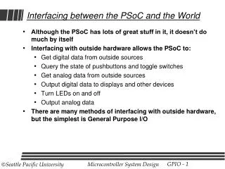
Programmable Routing/Interconnect Input / Output System • Three types of I/O • GPIO, SIO, USBIO • Any GPIO to any peripheral routing • Wakeup on analog, digital or I2C match • Programmable slew rate reduces power and noise • 8 different configurable drive modes • Programmable input threshold capability for SIO • Auto and custom/lock-able routing in PSoC Creator Up to 4 separate I/O voltage domains • Interface with multiple devices using one PSoC 3 / PSoC 5 device
Review You should now: Understand the high-level architecture of PSoC 3 / PSoC 5 Understand the CPU, Digital, Analog & Programmable Routing / Interconnect Subsystems
Lab Objectives Objectives: Blink an LED on the PSoC First Touch Kit Experience the PSoC Creator Design Flow
Section Objectives Objectives, you will be able to: Follow the PSoC Creator Design Flow and develop projects Find and use the tools available within the software IDE Compile, build and program PSoC 3 / PSoC 5 applications Debug PSoC 3 / PSoC 5 applications
PSoC Creator Design Flow Configure Start a new project Place components Configure components Connect components Develop Build hardware design and generate component APIs Write application code utilizing component APIs Compile, build and program Debug Perform in-circuit debug using PSoC Creator Reuse Capture working hardware/software designs as your own components for future use
Create a new project Select the platform Name the design Select the device* Select the sheet template* * Optional steps
Component Catalog Catalog Folders Analog ADC Amplifier DAC Digital Registers Functions Logic Communication Display System Catalog Preview Datasheet access
Component Configuration Double-click to open component configuration dialogs
Component Data Sheets Contents: Features General description of component When to use component Input/Output connections Parameters and setup Application Programming Interface Sample firmware source code Functional description DC and AC electrical characteristics
Design-Wide Resource Manager (.cydwr) Clocks Interrupts Set priority and vector DMA Manage DMA channels System Debug, boot parameters, sleep mode API generation, etc. Directives Over-ride placement defaults Pins Map I/O to physical pins and ports Over-ride default selections
Interrupts Priority may be changed Defaults to 7 (lowest priority)
DMA Priority may be changed Defaults to 2 (0 & 1 can consume 100% of bandwidth)
System System settings Debug settings Voltage Configuration
Clock Configurations Clocks are allocated to slots in the clock tree 8 digital, 4 analog Clocks have software APIs Reuse existing clocks to preserve resources
Build Process Generate a Configuration Design Elaboration Netlisting Verilog Logic Synthesis Technology Mapping Analog Place and Route Digital Packing Digital Placement Digital Routing <…there’s more…>