Download
1 / 22
240 likes | 830 Views
Materials Selection and Engineering Design of ITER PFCs. G. Federici ITER JWS Garching. Outline Highlights of PFC design & material selection Erosion during transient heat loads Remaining open questions Summary. 2 nd SOL and Divertor Physics ITPA Meeting,

E N D
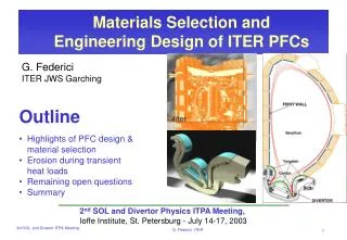
Materials Selection and Engineering Design of ITER PFCs G. Federici ITER JWS Garching • Outline • Highlights of PFC design & material selection • Erosion during transient heat loads • Remaining open questions • Summary 2nd SOL and Divertor Physics ITPA Meeting, Ioffe Institute, St. Petersburg - July 14-17, 2003 G. Federici, ITER
ITER Rationale for material selectionPresent choice: 3 different materials G. Federici, ITER
Strike points 0.56 2.35 1.34 4.23 3.47 ITER Divertor design loads/lifetime • Total power Q 150 MW • Nominal surface heat loads q = 10 MW/m2, = 400-500 sec, N = 3000 cycles (1st div.) • Transient heat load q = 20 MW/m2, = 10 sec, N = 300 cycles (i.e., 10%) • Disruption heat load Q = 10-100 MJ/m2, = 0.110 ms, N = 300 event (i.e., 10%) • Ion flux parameters J = 1021-1024 m-2s-1, E = 10-100 eV • Neutron load J(E>0.1MeV)1018 m-2s-1, D = ~0.1 dpa • Other factors electromagnetic loads (P 4 MPa), H environment, etc. W/m2 Code simulation of surface heat flux on divertor G. Federici, ITER
ITER Design assembly/maintenance • The PFCs and cassette body combine to provide adequate shielding to the vessel and the coils. • The divertor comprises 54 cassettes installed in ITER via 3 equi-spaced handling ports. • Each cassette consists of a cassette body onto which are mounted 3 PFCs. • These PFCs can be exchanged in hot cell in order to refurbish or to change the geometry of the divertor. • Several complete exchanges are foreseen during the life of ITER. • The cassettes are accurately positioned in the vessel such that each PFCs is aligned within ±2mm with respect to the PFCs on adjacent cassettes. G. Federici, ITER
Initial operation strategy Current strategy is to initially install CFC on the targets ITER • Tungsten has still uncertainties due to melt layer loss during disruptions and ‘large’ ELMs. • Maintain option to switch to an all-W divertor, prior or during T-operation. This option will be considered if • we do not succeed in mitigating the effects of T co-deposition (need to be to be determined during D-phase): • Design mitigation/temperature tailoring. • Mixed-material effects (=>need to use existing tokamaks). • we fail in developing reliable and effective techniques of in-situ tritium removal, which need to be demonstrated/tested in tokamaks. • there is substantial progress in mitigating heat loads during disruptions and ELMs. W CFC • Urgent need for development PMI diagnostics to be tested validated in existing tokamaks and during early operation with D in ITER. G. Federici, ITER
ITER First-wall design loads/lifetime • Total power Q 690 MW • Surface heat loads q = 0.25 MW/m2 (avg.) 0.5 max. = 400-500 sec, N = 30000 cycles • Disruption heat load None. • VDEs: q = 60 MW/m2, = 300 ms N=300 cycles (1%), • Neutron load 0.56 MW/m2 (avg.) / 0.78(max) D = ~1 dpa. • 412 blanket modules attached to the vessel. • ~4.5 t/module RH constraint. • steel shielding block • separate first wall panels. G. Federici, ITER
ITER Design assembly/maintenanceSeparate first-wall to minimise the operational waste • Each blanket module is connected to a permanent water cooling manifold by two pipes. • The FW part repairable and/or replaceable in hot-cell. • The modules are maintained by a special remotely driven in-vessel transporter inserted through the equatorial port. G. Federici, ITER
ITER Separate first-wall conceptsThe FW has 4 or 6 separate panels depending on the option chosen for FW attachment. • Option A: attachment with bolts and small shear ribs to support EM loads and to prevent sliding due to thermal expansion. • Option B: central beam attachment connected to the shield block on the rear side. G. Federici, ITER
ITER Remote handling classificationbased on need for scheduled and unscheduled maintenance and modifications, likelihood for maintenance, and impact on operations and availability Divertor is Class 1: • Requires scheduled maintenance or replacement. • Component design and RH equipment and procedures, optimised to ensure task completion within a minimum time. • Feasibility of maintenance tasks demonstrated with R&D during EDA. • Demonstration using real components during initial assembly prior to active phase of operation is highly desirable. Blanket is Class 2: • Do not require scheduled but likely unscheduled or very infrequent maintenance. • Components are designed for full remote repair or replacement but “minimisation of repair is subordinate to consideration on nuclear performance and reliability”. • Feasibility of maintenance tasks partially demonstrated with R&D during EDA. • Demonstration using real components during initial assembly prior to active phase of operation is desirable. G. Federici, ITER
ITER Maintenance time estimatesIn-vessel components are removed from the VV by 4 equatorial ports, 3 divertor ports and (?) upper ports (EC and diagnostics). • Divertor cassette refurbishment • 18 cassettes --> 1 RH port =>2 months (7 working day/week, 2 (8 hrs) wk shifts/day, 1 cask transporter (8 hrs/shift/day). • 3 RH ports in series ==> 6 months • Replacement of 1 single faulty cassette ≤ 2 months!! • Blanket maintenance • Replacement of some shield modules is likely due to local damage. • Replacement of the full first wall is presently not anticipated, but should be feasible. • 1 blanket module: 25 days • 1 toroidal row: 32-151 days* • All blanket modules: 276-916 days* *Depends on # of deployed IVT. • Current design policy: small number of spare parts. G. Federici, ITER
Critical PFC design/operation issues ITER • Heat loads and erosion during type I ELMs • Ongoing vigorous ITPA effort, EU PWI task force • Heat loads and erosion during thermal quench disruptions and VDEs • Ongoing vigorous ITPA effort, EU PWI task force • Hydrocarbon transport/T codeposition in remote areas and removal • Surveys in tokamaks (EU PWI task force) • Identify source and sinks. • Deposition patterns and dependence on operation parameters. • Composition of exhaust. • Laboratory simulations (EFDA, EU PWI task force) • Sticking of radicals. • Effects of temperature, H/C ratios, etc. • Mixing of materials (C/Be) G. Federici, ITER
Heat loads and erosion during type I ELMs Tolerable ELMs in ITER set by materials: TplateELM < physical limits (evap., melting). ITER Temp. excursions during ELMs=> no ratcheting!!! • Critical parameters are: • (1) energy loss from pedestal, • (2) fraction reaching the divertor, • (3) wetted area, • (4) duration/shape of ELM heat pulse. • Knowledge of these quantities still uncertain. Triang. ELMs, 0.3 ms, 1 MJ/m2 (1) BOL: 20 mm CFC, 10 mm W. (2) EOL: 2 mm CFC, 2 mm W. Only near-surface ≤400µm => Steep Temp. gradients G. Federici, ITER
Tolerable ELM size A large number of ELMs >1 MJ/m2 cannot be tolerated ITER ITER • In ITER: Wped ~ 100 MJ, nped ~8x10¹⁹ m-3, • Tped~3.5 keV, dw~10 cm =>low collisionality (n*ped ~0.04) • Scaling to ITER - DWELM/Wped: • n*ped : 15%-20% --> 15-20 MJ. • t//: 10%-15% --> 10-15MJ. • nped/nGW : 4%-5% --> 4 -5 MJ. • 50-70% of energy is deposited in divertor; • Wetted area: 4.5 -9 m2 with modest (~50%) broadening; • impact time > t// (~240 µs): tIR/ t// =1.5-3.1. • CFC and W show similar ELM erosion lifetime. Lifetime for W depends on melt layer loss. • Erosion lifetime shorter if one use a statistical evaluation of ELM parameters. • More inclined divertor target performs better. • Compatibility of inter-ELM plasmas with irregular W surface remains an issue. • Additional macroscopic erosion mechanisms due to high frequency pulsing and high temperature excursions localised in the near-surface (<400µm). G. Federici, ITER
A non-negligible fraction of the ELM energy from the main plasma reaches the main chamber wall ITER DWELMdiv ~ 50 – 80 % of DWELMdia Despite narrow l@ELMDWELMdiv/DWELM ~ 0.6 • Where does the Rest of DWELM go ? • Toroidal Asymmetries (probably No) • Main Chamber (probably Yes) • Transiently enhanced PRADELM (probably No) JET – Type I ELM G. Federici, ITER
Effects of type I ELMs at the main chamber wall ITER Expect interaction with protruding surfaces (~1 m2) ==> tolerable only 1-2 MJ depending on duration (if ≥ 1 ms no melting of W) G. Federici, ITER
Thermal Quench Disruptions Only a fraction of the energy reaches the divertor and is distributed rather uniformly. ITER Evolution of the surface temperature near and far from strike points in a DWth=5.6 MJ G. Matthews et al., 19th IAEA FEC 2002, Lyon To appear in Nucl. Fusion. • If the JET results extrapolate to ITER then disruptions would not damage a W target. • However, it is not known at the moment where and by what processes the missing and thermal an magnetic energies are deposited in the main chamber. • If this energy deposition is not sufficiently uniform, then additional damage to main chamber components might be expected. G. Federici, ITER
ITER thermal quench specifications Need to be revisited on the basis of the new findings (ongoing) ITER Case 1 Case 2 • If energy deposited in the divertor during disruptions is < 40% of the thermal energy with a broadening of the order 20-30 times, energy density at the target remains below the melting threshold for W. • Some shallow melting can nevertheless take place some times. • Concern remains on whether generation during ELMs/disruptions of surface irregularities in tungsten due to melting, and in CFC due to brittle destruction, might form hot spots during normal operation. G. Federici, ITER
Effects of ‘mitigated’ disruptionsAllowed time scale for energy dissipation (see talk of D. Whyte) ITER • The thermal energy density in ITER (plasma stored thermal energy/ wall surface area) is ~350 MJ/800m2 = 0.45 MJ/m2. • This energy density sets the minimum time in which the plasma thermal energy can be radiatively dissipated to the wall before melting/ablation occurs. • The allowed time scales for ITER w. Be first wall is closed to the limits set by the MHD time scale. • Assuming uniform (spatial and temporal) dissipation tlim≥0.5 ms. • Assuming a PF of 1.5-2 tlim≥2 ms. Melting as a function of deposited energy G. Federici, G. Strohmayer 3/2003 G. Federici, ITER
Parametric analyses of VDE effectsVDE parameters: 60 MJ·m-2, 300 ms, 1%UncertaintiesMelting - comparison Be and W ITER <10 MJ/m2 t≥500 ms avoid melting <10 MJ/m2 t>500 ms avoid melting Be <10 MJ/m2 t>100 ms avoid melting <10 MJ/m2 t>100 ms avoid melting W If t=500 ms no melting up to 30 MJ/m2 If t=500 ms no melting up to 70 MJ/m2 G. Federici, ITER
Parametric analyses of VDE effectsTemp. excursions at Cu interface - comparison Be and W ITER TCu melting Be TCu melting W Problems!! We need at least 5 mm W G. Federici, ITER
ITER Future Work/ Open Questions3-5 years before starting PFC material procurement for ITERCurrent efforts:EU task force on PWI / ITPA work • Type I ELM and disruption heat loads - energy loss, energy to divertor and wall, duration, broadening, impurities, etc.; (ITPA, JET TF, EU PWI TF) • Mitigation of disruptions (ITPA, JET TF, EU PWI TF); • Effect of mitigated disruptions on Be wall (ITPA); • Material damage due to ELMs/disruptions (Russia, EU PWI TF); • Erosion - mixed material effects (PISCES-B/EFDA) • Explain co-deposition in existing machines (ITPA, JET & EU PWI TFs); • Mitigation of co-deposition (temperature tailoring, reactive species (N2)); • Monitor CxHy deposits on cryopumps (JET, AUG); • Carbon removal - e.g. baking with oxygen - temperature, hold time (???); • Dust generation - volume, location, BET, mobilisation. • Plasma interaction with irregular and/or molten W surfaces. • Measurements/diagnostics G. Federici, ITER
ITER SummaryOpportunities and challenges • According to current ITER construction plans, 3-5 years are available for further R&D and physics input to divertor/first-wall design and PFM choice. • We take a big risk if we construct ITER without first testing/validating proposed material mix in an existing tokamak. • We should reduce to a minimum the extent that ITER has to be a PMI experiment and explore all these effects before hand in existing machines. • In case we retain CFC armour and use it during T operation a reliable method to remove the codeposted layers and control T-uptake is required. • Type-I ELMs are still challenging for the ITER divertor and design optimisation is ongoing. Power deposition on the first-wall is still uncertain. • IF JET divertor results extrapolate to ITER, the large majority of disruptions would not lead to melting a W target. Compatibility of plasma with irregular W surfaces and macroscopic C erosion and impact on operation/performance require investigations. • ITER divertor design has enough flexibility. Feasibility of maintenance has been demonstrated. For the first-wall only infrequent maintenance is anticipated and feasibility demonstration is needed. G. Federici, ITER