Download

1 / 15
150 likes | 1.62k Views
Design of an 8 Bit Barrel Shifter. Gene Vea, Perry Hung, Ricardo Rosas, Kevin Yoo Advisor: D. Parent May 11, 2005. Agenda. Abstract Introduction Why Simple Theory Back Ground information (Lit Review) Summary of Results Project (Experimental) Details Results Cost Analysis Conclusions.

E N D
Design of an 8 Bit Barrel Shifter Gene Vea, Perry Hung, Ricardo Rosas, Kevin Yoo Advisor: D. Parent May 11, 2005
Agenda • Abstract • Introduction • Why • Simple Theory • Back Ground information (Lit Review) • Summary of Results • Project (Experimental) Details • Results • Cost Analysis • Conclusions
Abstract • Summarize the logic, clock frequency, area, and power specs of your final design • We designed an 8-bit barrel shifter that operated at 200 MHz • 20mW of Power • Area of 370x350 mm2
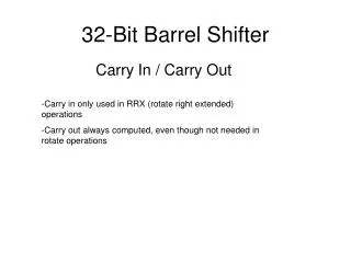
Introduction • The barrel shifter is a very important part of a combinational logic block. It was incorporated the 386 processor and is also used in microcontrollers. Intel has since moved on to software implemented barrel shifters in their Pentium 4’s but AMD still uses it to this day. • The designed circuit should shift a data word by any number of bits in a single operation. An N-bit shifter would require log2N number of levels to implement. For an 8 bit barrel shifter, it would require 3 logic levels.
Project Summary • Project was implemented with an array of 24 MUXs and 19 DFF MUXs arranged in three stages. • Implemented with the new DFF MUXs designed in class
Project Details • Explain all the details of your project. • Schematics should be legible, and not too busy. • If you did a set of experiments describe the conditions you did them under. • show a table with all hand calculations for your longest path • Show • Final schematic (not test bench) • Final layout • Final simulation
Cost Analysis • Estimate how much time you spent on each phase of the project • verifying logic (40 hours) • verifying timing (10 hours) • Layout (many hours 100+ hours) • Post extracted timing (3 hours)
Lessons Learned • Start early • Using the excel sheet to calculate Wn & Wp • Make sure to use the correct devices for layout if the same type of parts are used more than once. • Plan device schematic carefully and attack it part by part making sure that it works with the other parts of the circuit • Problems will always come up during LVS no matter how carefully it was wired together. • Because a device passes DRC does not mean that it will pass LVS when placed in layout
Summary • Barrel shifters have the ability to shift data words in a single operation over standard shift left or shift right registers that utilize more than one clock cycle. • Barrel shifters will continue to be used in smaller devices because it has a speed advantage over software implemented ones.
Acknowledgements • Cadence Design Systems • Synopsys • Prof. Parent • David Flores • Junghoon Kang