Download
1 / 52
590 likes | 1.07k Views
Measuring Temperature. ACADs (08-006) Covered Keywords Filled system thermometer, thermocouple, 3 wire resistance temperature detector, volatile fluid sensor. Description Supporting Material. Measuring Temperature. Terminal Objective:

E N D
Measuring Temperature ACADs (08-006) Covered Keywords Filled system thermometer, thermocouple, 3 wire resistance temperature detector, volatile fluid sensor. Description Supporting Material
Measuring Temperature Terminal Objective: Given the appropriate equipment and procedures, the I&C Technician will calibrate and maintain temperature instruments. Mastery will be demonstrated by successful completion of a Lab Performance Exercises and written Exam.
Describe the theory of operation of Filled System Thermometers • Describe the theory of operation of a thermocouple • Draw a diagram of a three wire RTD bridge circuit and explain it's operation • Check a Volatile Fluid sensor for proper operation per lab instructions • Given thermocouple tables or graphs, a millivolt meter, and a thermometer, determine the temperature of the measuring junction of a thermocouple within two degrees • Given a known Resistance Temperature Detector (RTD), it's type and it's temperature coefficient of resistance, calculate the RTD resistance for a given temperature, then verify the results in the lab setting
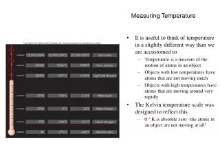
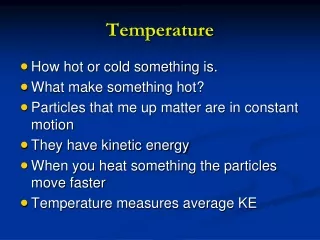
Class I - Liquid filled (excluding mercury) Class II - Vapor filled Class III - Gas filled Class V - Mercury filled Temperature is a measure of the average kinetic energy of the atoms of a substance
Operating Principles • Fill fluid expands as temperature increases, increasing in volume • Liquid in glass thermometers are also limited by the ability of glass to handle temperature extremes Mercury becomes solid at minus 39 degrees C Alcohol doesn’t freeze until -150 C Class I - Liquid filled (excluding mercury) Class II - Vapor filled Class III - Gas filled Class V - Mercury filled
Mercury thermometers can range from -38F to 1110 F Alcohol thermometers range from -328 F to 1110 F Other thermometer fill fluids include benzene & ether
Sensing element is a capillary tube filled with a liquid or gas which expands with an increase in temperature. This sensing element delivers a motion of physical change that is applied to the control element which either indicates, records, or by comparing the signal to a setpoint can be used to control the temperature of a process.
Class II (vapor filled) • Sensing bulb partially filled with volatile fluid • Common fluids include: methylchloride, ether, butane, hexane, propane, toluene, sulfur dioxide • Based upon the principle that in a system containing only a liquid and its vapor, at a given temperature, a given pressure will exist in the system, regardless of system volume • Actual temperature measurement occurs at interface between liquid and vapor • May exhibit erratic operation when temperature being measured swings above and below ambient • Offers good reliability, inherently accurate, non-uniform scales (non-linear) • Has mounting requirements
Class III (gas fill) • Utilizes perfect gas law • Absolute temperature = constant x pressure x volume • (Of course, in real life folume does not remain constant, and perfect gasses do not exist) • Helium approximates perfect gas, but tends to leak and is not often used • Nitrogen usually is used • Compensation generally not necessary if a large bulb is used
Two dissimilar metals bonded together • Metal A has a lower coefficient of thermal expansion than metal B • As temperature increases, metal B expands more than metal A • Frequently used in home thermostats, oven thermometers, mercury switches, indicators
Seebeck Effect A circuit formed from two dissimilar metals joined at both ends, develops an EMF (voltage) proportional to the difference in the two junction temperatures. So, if the temperature of one junction is kept at a known value, the temperature of the other junction can be determined by the amount of voltage produced.
Peltier Effect • Reverse of the Seebeck Effect
Law of Homogeneous Circuits (also known as the law of intermediate temperatures) • If thermocouple wire is homogeneous (all thermocouple wire between T1 and T2 and • If temperature at T1 is known, and temperature at T2 is known, • then the EMF will be known and will not be affected by temperature along the wire T2 T1
Law of Intermediate Metals • The algebraic sum of the thermo electromotive forces (EMF) in a circuit composed of any number of dissimilar metals is zero if the circuit is at a uniform temperature. -or- • You can use non-thermocouple wire as long as both intermediate junctions are at the same temperature without affecting the total EMF T2 T1 Thermocouple wire Thermocouple wire Non-thermocouple wire
How to take a thermocouple reading with a DVM Wrong way! (unless you are going to mathematically compensate for ref. junction temperature using thermocouple tables, or the DVM is set up to do self-compensation)
Reading a thermocouple • Read the millivoltage for the unknown measuring junction temperature • Obtain the millivoltage for the reference junction temperature from the applicable table. (reference junction is where the TC wire goes to copper) • Algebraically ADD the two millivoltages • The sum may then be converted to temperature directly from the same table. This is the unknown measuring junction temperature • The calculations are performed automatically whenever a thermocouple reading device is used. Usually done with a resistive temperature device
At Palo Verde we use type K thermocouples – Chromel/Alumel Polarity of thermocouple wire : all thermocouple leads have a red lead which is the negative lead
Resistance Temperature Detector • Electrical resistance of certain metals increase / decrease in a repeatable manner as temperature increases / decreases • No compensation or reference junction needed • Slower, but more accurate and more linear than thermocouples • The most commonly used metals for RTDs are Platinum, Copper, Tungsten and Nickel. At PV we use Platinum
Resistance Temperature Detectors Most RTDs at Palo Verde are 100Ω at 32F We have a few 200 Ω RTDs What’s this called?
Calculate Temperature using an RTD Where Rt2 = Resistance @ temp T2 in Ω Rt1 = Resistance @ temp T1 in Ω α = temperature/resistance coefficient (F or C) T2 = measurement temperature (F or C) T1 = reference temperature (F or C) usually 0C or 32F
Two Wire RTD • The RTD is one leg of a wheatstone bridge
Thermistors • Solid state device • Cheap • Similar to RTD except resistance goes down as temperature goes up. • Less linear than RTD • Often used in heat detection and compensation circuits • Higher sensitivity to small changes in temperature
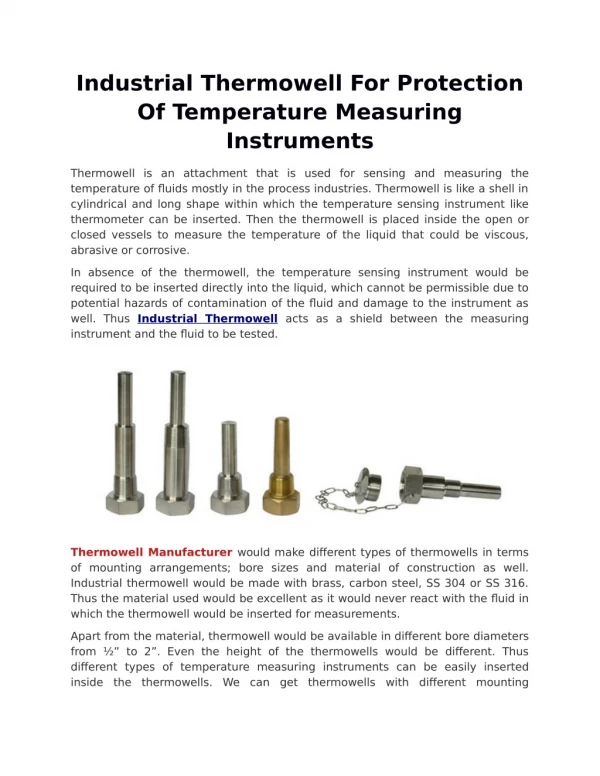
How can you tell if a thermocouple or RTD is in a thermowell? Thermowells
Discuss Plant Mod 2807626 Read about mod at end of temperature section in handout Discuss plant impact of mod This is required by a TCS action item
Instrument Loops • Identify common instrumentation signals • Explain the operation of a basic measurement loop • Explain the operation of a basic control loop
Common Instrument Signals • Current 4-20 milliamps • Voltage 0-10 Volts DC • Pneumatic 3-15 psig
DVMs are especially sensitive • Excessive voltage • Excessive current • Leads on wrong test point
Don’t trust your holding screwdriver, either to hold the lead or to keep you from getting shocked
When replacing a transmitter, beware! You are typically using a 3-valve manifold as your pressure boundary.