Download
1 / 50
1.13k likes | 2.04k Views
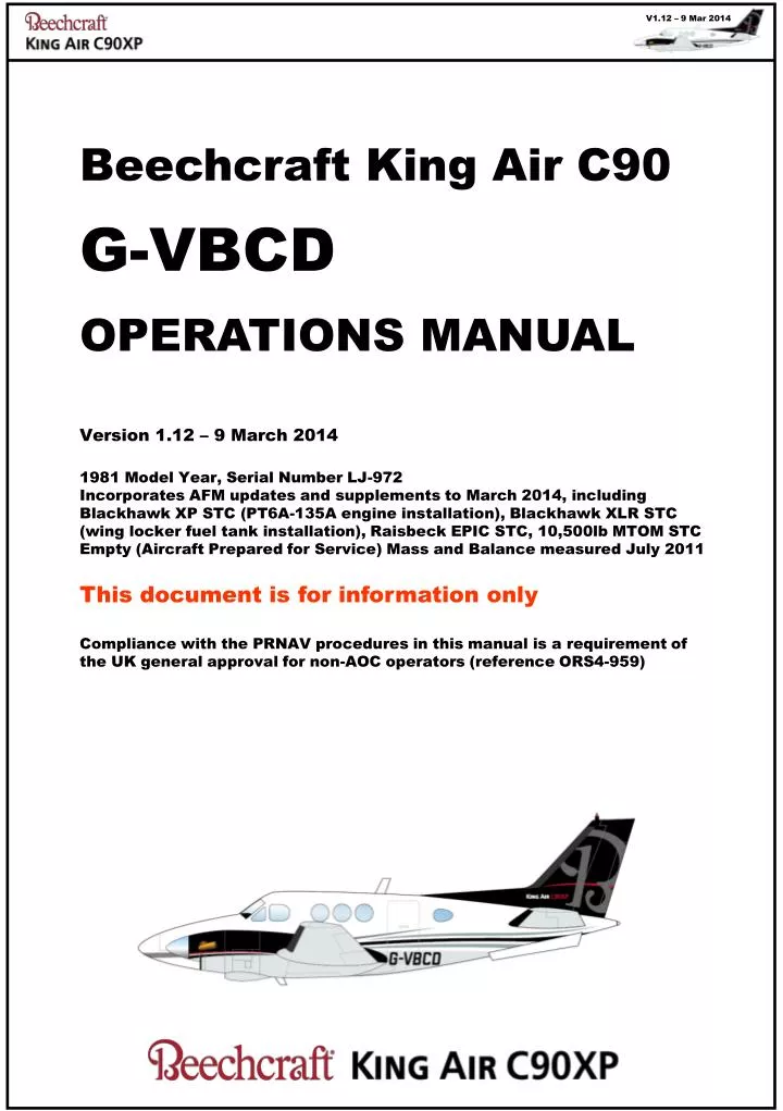
Beechcraft King Air C90 G-VBCD OPERATIONS MANUAL Version 1.12 – 9 March 2014 1981 Model Year, Serial Number LJ-972

E N D
Beechcraft King Air C90 • G-VBCD • OPERATIONS MANUAL • Version 1.12 – 9 March 2014 • 1981 Model Year, Serial Number LJ-972 • Incorporates AFM updates and supplements to March 2014, including Blackhawk XP STC (PT6A-135A engine installation), Blackhawk XLR STC (wing locker fuel tank installation), Raisbeck EPIC STC, 10,500lb MTOM STC • Empty (Aircraft Prepared for Service) Mass and Balance measured July 2011 • This document is for information only • Compliance with the PRNAV procedures in this manual is a requirement of the UK general approval for non-AOC operators (reference ORS4-959)
GENERAL INFORMATION NORMAL PROCEDURES EMERGENCY PROCEDURES OPERATING INFORMATION
General Information Owner and Operators Intentionally blank in this version CAMO Intentionally blank in this version EGHH and EGLK Contact Details Intentionally blank in this version Flight Plan filing Intentionally blank in this version
Flight Plan information Item 8 I—IFR, V—VFR Y—IFR then VFR, Z—VFR then IFR In item 15, specify transition point Item 10 SDFGRS/S S for VHF, VOR, ILS B for LPV (APV SBAS) – not at present D for DME, F for ADF, G for GNSS R for PBN approved (see Item 18) Y for 9.33kHz/S for Mode S Item 15 Speed or altitude change—enter the point followed by a slash and new speed or altitude (e.g., LN/N0200A045). Flight rule change—enter the point/designator followed by a space and the new flight rule (e.g., LN VFR, LN/N0200A045 IFR, etc.). • Item 18 (from Nov 12) • For PBN capability enter PBN/B2D2S1 • B2 - RNAV 5 GNSS • D2 - RNAV 1 GNSS • S1 - RNP APCH • For SBAS enter NAV/SBAS
Specs & Limitations (see AFM) ENGINE OIL Total capacity14 qts each engine Refill capacity12.5 qts each engine Operating level 9.5 – 12.5 qts each engine FUEL Minimum fuel for take-off 265lbs per wing & above yellow arc Approved Fuel:Jet A, A-1, B and JP4,5 Capacity: Mains plus Locker384 USg plus 78USg; total 462 USg 1454litres plus 295litres; total 1749litres 2570lbs plus 520lbs; total 3090lbs Quantities are Useable. Anti-ice additive not req’d. See AFM for use of Avgas. TIRE PRESSURES51-55 psi Nose, 67-73 psi Mains(*) (* 10 ply tires fitted, required for operation at increased MTOM 10,500lbs) MAXIMUM OPERATING ALTITUDE Maximum30,000’ Without Oxy equipment25,000’ Above 25,000’, all occupants must have a 10min Oxy supply available Pressure Differential0-4.7 PSI normal, 4.7 PSI max
GENERAL INFORMATION NORMAL PROCEDURES EMERGENCY PROCEDURES OPERATING INFORMATION
NORMAL PROCEDURES 1 Airspeeds for Normal Operation • Air Minimum Control Speed (VMCA)………. • Vr and V1…………………......................... • Initial Climb (2 Engine, Vy)……………… • Intentional One Engine Inoperative • Speed (VSSE) ............................................ • Two-engine Best Angle-of-Climb (Vx)……. • Two-engine Best Rate-of-Climb (Vy)…… • Maximum Maneuvering Speed (VA)……… • Turbulent Air Penetration .......................... • Landing Approach VREF…….....…..…….. • ICAO Approach Category………………….. • Balked Landing Climb .............................. • Maximum Demonstrated Crosswind……… • Cruise Climb: • Sea Level to 10,000 feet…………… • 10,000 to 20,000 feet………………. • 20,000 to 25,000 feet………………. • 25,000 to 30,000 feet………………. • VmoMax Operating Speed……………….. • VfeMax Flaps Extended…………………… • VloMax Gear Operation………………....... • VleMax Gear Extended…………………… • Vso (bottom of White Arc)…………………. • Vs1 (bottom of Green Arc)………………… 90 KIAS 95 KIAS 110 KIAS 97 KIAS 100 KIAS 110 KIAS 170 KIAS 160 KIAS 100 KIAS B 95 KIAS 25 KIAS 150 KIAS 140 KIAS 130 KIAS 120 KIAS 208 KIAS 178 KIAS (APP, 35%) 130 KIAS (FULL, 100%) 156 KIAS – Extend 130 KIAS – Retract 156 KIAS 76 KIAS 89 KIAS Amended by Operator with 10KIAS increment over AFM due PT6A-135A observed performance
NORMAL PROCEDURES 2 • Propeller………CHECK • Engine Air and Oil Cooler Intakes…………CLEAR Ice Vane……….CHECK • Engine Boot......CHECK • Engine Oil……..CHECK • Fuel Filter….…..DRAIN • Cowling………...CHECK • Nacelle Fuel Tank • ………………CHECK • Heat Exchanger CLEAR • Transfer Pump Sump …………………DRAIN • Antennas and Beacon …………………CHECK • Ram Air Inlet…...CLEAR • Baggage Door.SECURE • Air Con Ducts….CLEAR • Nose Gear……..CHECK • Landing &Taxi Lights • …………….CHECK • Pitot Covers…REMOVE • Windshield Wipers • …………….CHECK • Transfer Pump Sump …………………DRAIN • Heat Exchanger CLEAR • Nacelle Fuel Tank • ………………CHECK • Propeller………CHECK • Engine Air and Oil Cooler Intakes…………CLEAR Ice Vane……….CHECK • Engine Boot......CHECK • Engine Oil……..CHECK • Fuel Filter….…..DRAIN • Cowling………...CHECK 3 4 2 External inspection 5 1 • Boost Pump Sump DRAIN • Landing Gear….. CHECK • Wheel Well Sump DRAIN • Outboard Wing Sump • ………………DRAIN • Wing Fuel Tank... CHECK • Chocks…………REMOVE • Deice Boot…….. CHECK • Wing Tip (Lights) CHECK • Aileron and Tab CHECK • Flaps………… CHECK • Locker Fuel Tank CHECK • Locker Fuel Tank CHECK • Flaps………… CHECK • Aileron and Tab CHECK • Wing Tip (Lights) CHECK • Stall Warning… CHECK • Deice Boot…….. CHECK • Chocks…………REMOVE • Wing Fuel Tank…CHECK • Outboard Wing Sump • ……………....DRAIN • Wheel Well Sump DRAIN • Landing Gear….. CHECK • Boost Pump Sump DRAIN 6 • Oxygen Door …..SECURE • Static Ports…….CLEAR • Access Panels…SECURE • Deice Boots…….CHECK • Elevator…………CHECK • Fin fittings………CHECK • Static Ports…….CLEAR Cabin Checks 1. Aft area………………….. LIFERAFT & 1ST AID KIT 2. Cabin……………………. LIFEJACKETS, OXY MASKS & AMENETIES 3. Fwd Partition...…………. TECH LOG & AFM 4. Cockpit………………….. OXY MASKS, FIRE EXTING, TORCH
NORMAL PROCEDURES 3 Before Starting Engines • 1. Cabin Door LOCKED • Baggage SECURE (Mass & Balance checked) • Emergency Exit SECURE • Seats & Harnesses POSITIONED; UPRIGHT, FASTENED • Passengers BRIEFED • 6. Parking Brake SET • 7. Control Locks REMOVE • 8. Pedestal Circuit Breakers IN • 9. Overhead Panel CHECK • 10. Oxygen Control ON then OFF • 11. Oxygen System Pressure CHECK • 12. Emergency Static Air Valve NORMAL • 13. Right Circuit Breaker Panel CHECK • 14. Cabin Temp Mode OFF; Vent Blower AUTO, Elec’ Heat OFF • 15. Landing Gear Handle DOWN • 16. Condition Levers CUT OFF • 17. Propeller Levers FULL FORWARD or FEATHER • Power Levers IDLE • Engine Ice Vanes EXTENDED (handles pulled out) • Left Subpanel Switches OFF • 21. Start Clearance Battery & Avionics ON, as req'd, then OFF • 22. Fuel Panel CHECK • a. Circuit Breakers IN • *b. Fuel Valves (Firewall) CLOSED • *c. Crossfeed OPEN, FUEL CROSSFEED lit, CLOSED • d. Boost Pumps ON (listen for operation) • Battery Switch ON, check FUEL PRESSURE lights on • e. Fuel Valves (Firewall) OPEN, check FUEL PRESSURE lights off • f. Fuel Quantity CHECK • *g. Transfer Pumps ON (listen for operation), then OFF • 24. Locker Fuel Panel Switches OFF, CBs in, Test Lights • Voltmeters CHECK Battery Volts • 26. Cabin Sign Switch NO SMOKE & FSB *May be omitted at Pilot’s discretion for quick turnaround No voltage on one side indicates current limiter out
NORMAL PROCEDURES 4 Engine Starting • External lights ON as required • Right Ignition Start Switch ON, RH ING INDon • ……….after Ng rpm stabilizes for 5s, 12% minimum;17% normal • 2. Right Condition Lever LOW IDLE • ITT and Ng MONITOR ITT 1090°C maximum • ……….at Ng 60% or above • Right Start Switch OFF • Right Condition Lever HIGH IDLE if required • Right Generator ON unless external power is used • Right Oil Pressure CHECK correct indication if prop unfeathered • ……...after Right Generator load falls below 50% • Right Generator OFF • Note LJ972 AFM: If req’d, Left Engine may be started with Right Generator ON, • or Right Generator may be turned ON after the LH Start Switch is engaged • Left Start Switch ON, LH ING INDon • ……….after Ng rpm stabilizes for 5s, 12% minimum;17% normal • 2. Left Condition Lever LOW IDLE • ITT and Ng MONITOR ITT 1090°C maximum • ……….at Ng 60% or above • Left Start Switch OFF • Left and Right Generators BOTH ONunless external power is used • Left Oil Pressure CHECK correct indication if prop unfeathered • External Power disconnect and Engine Clearing – see Normal Procedures 9 After Engine Starting Transfer Pumps ON Crossfeed Switch AUTO DC Volt and Loadmeters CHECK Inverter CHECK BOTH and SELECT inverter Avionics Master Switch ON Lights AS REQUIRED Fuel Control Heat ON Cabin Temp and Mode AS REQUIRED (observe gauge limits) Annunciator Lights TEST then CLEAR
NORMAL PROCEDURES 5 Before Taxi • Engine Ice Vanes CHECK EXTENDED (handles pulled out) • Baro setting ATIS copied, G600 and Altimeter SET • GTN650 Self-test & database CHECK • Other Instruments CHECK • Propellers Max RPM, Prop Sync OFF • Brakes CHECK • Parking Brake SET • Boost Pumps and Auto Crossfeed • Left Boost Pump OFF • LH FUEL PRESS off, FUEL CROSSFEED on • b. Left Boost Pump ON • c. Crossfeed CLOSED then AUTO • d. Right Boost Pump OFF • RH FUEL PRESS off, FUEL CROSSFEED on • e. Right Boost Pump ON • f. Crossfeed CLOSED then AUTO • Avionics and Radar CHECK, radar to STBY if reqd • Pressurization SET switch, rate knob & Alt to Cruise +500’ • Autopilot CHECK, then OFF • Electric Elevator Trim CHECK • a. Tab Control Switch ON • b. Pilot's and Co-pilots' Switches CHECK OPERATION • c. Trim Disconnect CHECK DEACTIVATION OF SYSTEM • d. Tab Control Switch OFF then ON • Trim Tabs SET • Flaps CHECK AND SET UP • Flight Controls CHECK • Autofeather TEST at Lo Idle then ARM • Autofeather test: Set Power to 500 ft-lbs, hold test switch • L Autofeatherand R AutofeatherIlluminated • Individually each engine: Retard power, @400ft-lbs opposite annunciator extinguishes • @260lbs, both annunciators extinguish and prop feathers • 11. Manual Prop Feathering CHECK at Lo Idle Before Take-Off Continue with item 12, “Before Take-Off CONTINUED” procedure
NORMAL PROCEDURES 6 Before Take-Off CONTINUED *May be omitted at Pilot’s discretion for quick turnaround • 12. Run-Up TEST * • Propeller Controls Fully FWD, Max RPM • Power Levers IDLE • Governor Test Switch HOLD in TEST position • LH Power Lever Increase RPM to 1750, stabilize • LH Power Lever Advance, check 1750rpm maintained • Governor Test Switch Release • LH Prop Lever Retard then fully FWD to check • Vacuum and Pneumatic CHECK Gauge pressure • LH Engine Ice Vane RETRACT, check Torque drop, EXTEND • LH Power Lever IDLE • Repeat steps c-j for RH Engine • Friction LocksSET • Fuel System Boost & Transfer Pumps ON • Crossfeed AUTO, recheck Quantity • Instruments CHECK • Auto Ignition ARM • Autofeather ARM • Bleed Air Valves OPEN • IFR Departure Checks after clearance copied • HDG bug SET to runway heading • Departure procedureLOADED, CHECKED • G600 CDI mode SET, CDI on initial track • Altitude Selector SET to cleared level • BaroSET, to 1013 if cleared to FL • TOGA switch PRESS, check Flight Director cue • >>> Departure Brief (Wx, Wind & Temp, Distances, Vr, V1, Alternate) • After Line-Up Clearance • Ice Protection ON (Hot 5, Windshield and as reqd) • Landing Lights ON Take-Off Power Levers ADVANCE, limit to 1520 ft-lbs Torque Rotate at 95 KIAS Landing Gear RETRACT with positive climb
NORMAL PROCEDURES 7 Climb • Climb Power SET 1300 ft-lb • Propeller 1900 RPM, Sync ON • Alt Selector SET and ARM • Baro setting CHECK • Landing Lights OFF • when workload permits • Autofeather Switch OFF • Auto Ignition OFF when not in visible moisture • Engine Ice Vanes RETRACT when not in visible moisture • Engine Instruments MONITOR • Cabin Sign AS REQUIRED • Pressurization CHECK, SET rate as desired CAUTION Alt Selector and Autopilot are coupled to analogue P1 Altimeter, not G600 Cruise • Altitude CHECK • Power SET • Gauges CHECK (Fuel, Battery, Engine, Press’n) • Ice Protection CHECK and SET as required • Navigation Update avionics as appropriate • Communication As appropriate • Weather Radar, Stormscope, ATIS as appropriate Descent Pressurization SET rate & outer scale to Field Elev +500’ Altimeters CHECK, SET Baro Altitude Selector SET and ARM Ice Protection As required Arrival Radios SET, copy ATIS Arrival and Approach LOAD procedure, BRIEF Altimeters CHECK, SET Baro Pressurization CHECK Ice Protection As required Fuel CHECK Cabin Secure, Seat back & Harnesses, Sign
NORMAL PROCEDURES 8 Initial Approach • Engine Ice Vanes EXTEND • Auto Ignition ARM • Auto Feather ARM • Propeller 1900 RPM • Prop Sync OFF • Pressurization CHECK • Flaps APPROACH (below 178 KIAS) Final Approach and Landing • Landing Gear DOWN (below 156 KIAS) 3 GREENS • Landing Lights ON • Ice CHECK • Condition Levers LO or HIGH IDLE as required • Propellers MAX RPM • Power Levers SET • When Landing Assured FLAPS DOWN FULL (below 130 KIAS) • After Landing POWER in BETA or REVERSE as reqd Go-Around TOGA switch PRESS Power Levers MAX POWER (1520 lbs-ft) Airspeed 95 KIAS or above Flaps UP Gear UP After Landing LightsLanding OFF, Taxi ON Auto IgnitionOFF Auto Feather OFF Ice Protection OFF, Engine Ice Vanes stay EXTENDED Flaps UP Trim SET Electrical load Observe Limits
NORMAL PROCEDURES 9 Shutdown and Securing • Parking Brake SET • Transfer Pumps OFF • Crossfeed CLOSED • Inverter OFF • Avionics Master Switch OFF • Subpanel Switches OFF • Cabin Mode Control OFF • Blower AUTO • Bleed Air Valves CLOSED • Oxygen Supply Control OFF • ITT BELOW 585°C FOR ONE MINUTE • Propellers FEATHERED • Condition Levers CUT-OFF • Boost Pumps OFF below 10% Ng or less • DC Volt Loadmeters CHECK VOLTAGE • (No voltage onone side indicates current limiter out) • Battery and Generators OFF • Tech Log UPDATE • Control Lock FIT onlyif aircraft will not be towed • Cabin Lights CHECK OFF • External Covers & Chocks INSTALL as required Other Normal Procedures: After Start • External Power (if used) DISCONNECT, access door SECURED • Right Generator ON • Battery Condition CHECK • Left Generator ON • Engine Clearing • Condition Lever CUT-OFF • Ignition and Engine Start Switch OFF • Battery Switch ON • Boost Pump ON • Ignition and Engine Start Switch STARTER ONLY (min of 15 seconds) • Ignition and Engine Start Switch OFF • Boost Pump OFF
NORMAL PROCEDURES 10 RNAV 1 or PRNAV Operating Procedures • This aircraft has navigation equipment installed and approved for PRNAV & RNAV 1 • This procedures on this page have been written in accordance with JAA TGL10 • When these procedures are used, and when the Pilot-in-Command has had suitable ground training in accordance with TGL10, for Private (non-AOC) operation the aircraft is PRNAV and RNAV 1 compliant through the provisions of UK CAA ORS4-959 • The ICAO FPL codes are thus Item 10: SBDFGR/SItem 18: PBN/B2D2S1 NAV/SBAS • Jeppesen hold a Type 2 LoA for the databses used in the GTN650s, thefore databse integrity checks for private operation are not required other than as detailed below A. Pre-Flight (in addition to Normal Procedures) • Check NOTAMs for EGNOS and GPS serviceability and coverage • Check currency and coverage of GTN650 databases B. Before Take-Off (in addition to Normal Procedures) • Check both GTN650s self-test and check WAAS enabled • IF WAAS/EGNOS unavailable, perform GTN650 RAIM prediction • Enter Flight Plan and select Departure Procedure • Crosscheck procedure legs listed in the GTN650 with Jeppesen chart • Select GPS CDI mode in G600, check CDI slews to first track • Perform GPS position check on runway • After take-off • Monitor tracking on G600 CDI scale (1nm) and GTN650 Integrity Annunciator • Crosscheck RNAV guidance with conventional aids C. Arrival (in addition to Normal Procedures) Select and load the Arrival Procedure in GTN650 #1 Crosscheck Procedure map display with Jeppesen charts Select GPS CDI mode in G600, check CDI slews to first track Prepare and brief the alternative non-PRNAV procedure Complete gross error check using radio navaids Monitor tracking on G600 CDI scale (1nm) and GTN650 Integrity Annunciator RNAV 1 Capability Failure (eg. LoI alert) Total failure of one GTN650 1. Revert to the working GTN650 2. Notify ATC In the event of an LoI alert, monitor the GTN650s for 1 minute, then initiate the procedures below Loss of Integrity or other loss of RNAV 1 capability in both GTN650s 1. Select radio navigation aids and CDI source 2. Cancel GPS Roll Steer mode if engaged 3. Advise ATC and continue with non-RNAV procedure or as directed
NORMAL PROCEDURES 11 XLR Fuel Locker Notes • Locker useable fuel quantity is 260lbs (148l) per tank, total 520lbs (296l) • CAUTION • Do not transfer fuel from either Locker Tank when there is less than 400lbs of available fuel space in each Wing Tank • Avoid partial transfer of Locker fuel • Max lateral imbalance of combined Main and Locker fuel is 200lbs • LH and RH transfer should be concurrent to avoid imbalance • If Locker Fuel quantity is uncertain; complete the fuel transfer, or drain or fill the tanks so that they are known to be full or empty • Fuel Gauges CHECK >400lbs space each Wing tank • Locker Fuel Pumps L & R both ON • LOCKER PUMP ON Lights L & R both continuously illuminated • Wing Fuel Quantity Monitor L & R Fuel Gauges for increase • Timing Note, transfer takes ~20mins • When L & R NO LOCKER XFR lights have illuminated: • Locker Fuel Pumps L & R both OFF • Annunciators CHECK all OFF • Fuel gauges CHECK • Flight planning CHECK range and endurance • Verify fuel state is consistent with successful transfer by correlating fuel gauge readings before and after transfer with engine fuel burn during transfer. Record Locker Tanks as empty in aircraft Tech Log Locker Fuel Transfer “NO LOCKER XFR” Light Illumination If the “NO LOCKER XFR” light illuminates other than upon expected completion of a transfer, it is most likely that the illuminated-side pump has failed, or the system has clogged or a fuel leak has occurred: Locker Fuel Pumps L & R both OFF Fuel gauges CHECK Flight planning RE-VERIFY range and endurance
NORMAL PROCEDURES 12 KFC250 Autopilot Operating Notes (see AFM Supp for full detail) Limitations: • Autopilot operation is permitted up to Vmo (208 KIAS) • Do not use the autopilot below the following altitudes: • Approach: 200ft AGL Climb: 500ft AGL Other: 1000ft AGL • Do not use the autopilot or yaw damper during take-off or landing • Engage Procedure: use the Mode Controller in center pedestal • Select the FLT DIR mode • Push the AP engage lever to ON • Disengage Procedure • Hold control wheel firmly, and monitor FD for unsatisfied commands or pitch mis-trim • Push the Pilot’s AP YD DISC/TRIM INTRPT switch • ALT HOLD operation • Press ALT switch on Mode Controller, observe ALT annunciator • Pressure altitude from P1 analogue altimeter at time of engagement will be held • Alternatively, use KAS297 ALT SELECT and ARM functions • ALT HOLD level change • In ALT mode, press & hold the VERTICAL TRIM switch on the mode controller to climb or descend ~600fpm and hold altitude at moment of switch release • Or, disengage ALT mode, enter climb or descent using VERTICAL TRIM and capture new altitude manually or with ALT SELECT and ARM • GPS Roll Steer Operation • The Roll-Steer Selector/Annunciator left of the G600 toggles the autopilot’s HDG error source in HDG mode between the G600 heading bug and the roll steer output of the GDU620 when GPS1 or GPS2 source is displayed • Roll-Steer mode is indicated by the GPSS symbol • on the left edge of the G600 PFD • NAV or APPR mode operation • Select Nav source on G600 using CDI key, set desired course with CRS key • Press NAV or APPR mode to intercept course and observe ARM annunciator • Note CPLD annunciator when course intercepted and tracking coupled • GS operation – only in APPR CPLD operation with BCK CRS mode OFF • GS CPLD mode automatically engages intercepting a valid glideslope signal • GS CPLD mode disengages when any other vertical mode is selected KFC250 Autopilot Emergency Procedures • EMERGENCY DISENGAGE OF AUTOPILOT AND ELEC TRIM • Control Wheel HOLD FIRMLY • AP YD DISC/INTRPT button PRESS AND HOLD, re-trim manually • Avionics Master switch OFF, AP YD DISC/INTRPT button RELEASE • AP TRIM circuit breaker PULL • Avionics Master switch ON • ENGINE FAILURE • Disengage Autopilot, follow appropriate Emergency Procedure • Aileron and Rudder axes must be manually trimmed before Autopilot engagement in One Engine Inoperative flight
GENERAL INFORMATION NORMAL PROCEDURES EMERGENCY PROCEDURES OPERATING INFORMATION
EMERGENCY PROCEDURES 1 Emergency Airspeeds Air Minimum Control Speed (Vmca)………….. Intentional Single-Engine Speed (Vsse) ........ Single-engine Best Angle-of-Climb (Vxse)……. Single-engine Best Rate-of-Climb (Vyse)… Maximum Maneuvering Speed (Va)………… Turbulent Air Penetration ............................. Maximum Range Glide Speed……...………. 90 KIAS 97 KIAS 100 KIAS 110 KIAS 170 KIAS 160 KIAS 100 KIAS Engine Failure • ENGINE FAILURE AFTER TAKE-OFF – insufficient runway • Pitch UP> Power UP> Flap UP> Gear UP • Maintain 100 KIAS and control yaw • Identify failed engine – power lever IDLE • Shutdown failed engine • EMERGENCY ENGINE SHUTDOWN in the event of: • Engine Failure in flight • Engine Fire in flight • Engine Torque increase – uncontrolled, in ground or flight • Illumination of CHIP DETECT annunciator • Affected Engine: • Condition Lever CUT-OFF • Propeller Lever FEATHER • Fuel Firewall Valve CLOSED • Secure inoperative engine: • Bleed Air Valve AS REQUIRED • Engine Auto Ignition OFF • Boost Pump OFF • Fuel Transfer Pump OFF • Crossfeed CLOSED • Generator OFF • Fuel Control Heat OFF • Autofeather OFF • Propeller Synch OFF • Electrical Load MONITOR
EMERGENCY PROCEDURES 2 Engine Fire on Ground • Affected Engine: • Condition Lever CUT-OFF • Fuel Firewall Valve CLOSED • Starter Switch STARTER ONLY • Boost Pump OFF • Fuel Transfer Pump OFF • Crossfeed CLOSED Engine Failure During Ground Roll • Power Levers IDLE • Brakes As Required • If insufficient runway remains for stopping: • Condition Lever CUT-OFF • Fuel Firewall Valve CLOSED • Master Switch STARTER ONLY • Boost Pumps OFF Engine Failure In-Flight below Vmca 90KIAS • Reduce power on operative engine as req’d to maintain control • Lower nose to accelerate above minimum control speed • Adjust power as required • Secure affected engine as per EMERGENCY ENGINE SHUTDOWN Flame-Out of Operating Engine during One-Engine Inoperative Flight • Power Lever IDLE • Propeller DO NOT FEATHER • Condition Lever CUT-OFF • Conduct AIR START procedures – see Emergency Procedures 3
EMERGENCY PROCEDURES 3 Air Start – STARTER ASSIST • Electrical Load REDUCE (eg. Radar, Anti Ice, Cabin Temp Mode OFF) • Power Lever IDLE • Condition Lever CUT-OFF • Fuel Panel CHECK • Fuel Firewall Valve OPEN • Boost Pump ON • Transfer Pump ON • Crossfeed AUTO • Start Switch ON (up) Check IGNITIONlight ON • Condition Lever LOW IDLE (8 seconds after start switch ON) • Start Switch OFF (Ng above 51%) • Generator RESET momentarily, then ON • Propeller AS REQUIRED • Power Lever AS REQUIRED • Fuel Control Heat ON • Electrical Equipment AS REQUIRED Air Start – WINDMILLING ENGINE AND PROP • Electrical Load REDUCE (eg. Radar, Anti Ice, Cabin Temp Mode OFF) • Power Lever IDLE • Propeller MAX RPM • Condition Lever CUT-OFF • Fuel Panel CHECK • Fuel Firewall Valve OPEN • Boost Pump ON • Transfer Pump ON • Crossfeed AUTO • Generator (Inop Engine) OFF • Airspeed ABOVE 140 KIAS • Altitude BELOW 20,000 ft • Auto-Ignition ARM • Condition Lever LOW IDLE (8 seconds after Auto-Ign ARM) • Power and Prop LeversAS REQUIRED (after ITT has peaked) • Auto-Ignition OFF • Fuel Control Heat ON • Electrical Equipment AS REQUIRED
EMERGENCY PROCEDURES 4 Smoke or Fire or Fumes • Smoke and Fume elimination • Attempt to Identify the source of smoke or fumes. Smoke associated with electrical failures is usually gray or tan in color, and irritating to the nose and eyes. Smoke produced by environmental system failures Is generally white in color, and much less irritating to the nose and eyes. • ELECTRICAL SMOKE OR FIRE • Oxygen Control handle ON, Masks ON • Cabin Temp Mode OFF • Vent Blower AUTO • Avionics Master OFF • Nonessential Electrics OFF • If smoke or fire ceases • Individually restore avionics & electrics, isolate defective equipment • If smoke or fire persists • Cabin Pressure switch DUMP • Land as soon as practical • ENVIRONMENTAL SYSTEM SMOKE OR FUMES • Oxygen Control handle ON, Masks ON • Cabin Temp Mode OFF • Vent Blower HI • LH Bleed AirCLOSED • If smoke decreases • Continue operation with LH Bleed Air closed • If smoke does not decrease • LH Bleed Air OPEN • RH Bleed Air CLOSED • If smoke decreases, continue operation with RG Bleed Air Closed Emergency Descent • Power Levers IDLE • Propeller Controls MAX RPM • Wing Flaps APPROACH • Landing Gear EXTEND • Airspeed 156KIAS maximum
EMERGENCY PROCEDURES 5 Landing Emergencies • ONE ENGINE INOPERATIVE LANDING • When it is certain that the field can be reached: • Flaps APPROACH • Landing Gear DOWN • Propeller Controls FULL FORWARD • Airspeed 110 KNOTS • When It is certain there is no possibility of go-around: • Flaps DOWN • Airspeed 100 KNOTS • Execute Normal Landing • ONE ENGINE INOPERATIVE GO-AROUND • Power MAXIMUM ALLOWABLE • Flaps UP • Landing Gear UP • Airspeed 107 KNOTS Glide (both engines inoperative) • Flaps UP • Landing Gear UP • Propeller Controls FEATHERED • Airspeed 150 KNOTS Landing Gear Manual Extension • Airspeed ESTABLISH 120 KNOTS • Landing Gear Relay CB PULL (next to Gear handle, not on CB panel) • Landing Gear Handle DOWN • Emergency Engage Handle: • LIFT AND TURN CLOCKWISE TO THE STOP TO ENGAGE • Extension Lever • PUMP up and down until the 3 green gear down lights are lit • Retraction after practice manual extension ONLY: • Emergency Engage handle rotate counter clockwise and push down to stow • (ii) Extension lever stow (iii) Gear CB in (iv) Gear handle Up
EMERGENCY PROCEDURES 6 Low Oil Pressure • Oil Pressure values between 40 and 80 psi are undesirable: they should be tolerated only for the completion of the flight, and then only at a reduced power setting. • Oil pressure values below 40 psi are unsafe; they require either that the engine be shut down, or !hat a landing be made as soon as possible, using the minimum power required to sustain flight. Fuel System Emergencies • BOOST PUMP FAILURE • Inoperative Boost Pump OFF • Determine whether continuation of flight with Crossfeed open is possible (refer to Flight Manual) • To continue flight with Crossfeed closed, satisfactory operation may be obtained by reducing power, descending to a lower altitude, waiting for fuel to cool • CROSSFEED (One Engine Inoperative operation) • Fuel Boost Pumps Both ON • Transfer Pumps ON • Crossfeed switch OPEN, Check FUEL CROSSFEED on • NON-FEEDING tankFuel Boost Pump OFF and check • non-feeding side FUEL PRESS unlit • TO DISCONTINUE CROSSFEED • Fuel Boost Pumps Both ON • Crossfeed switchCLOSED • Fuel Boost PumpOFF (inoperative engine only) NOTE: The Crossfeed system is designed solely for operation in the event of a Fuel Boost Pump failure or an Engine failure. The normal position of the Crossfeed switch with both engines running is AUTO with the FUEL CROSSFEED annunciator unlit Uncommanded Electric Pitch Trim operation • Attitude CONTROL MANUALLY • AP/Trim Disconnect Switch DEPRESS FULLY • Manually re-trim airplane • ELEV TAB switch (pedestal) OFF
EMERGENCY PROCEDURES 7 Electrical System Failure • GENERATOR INOPERATIVE (DC GEN annunciator lit) • Starter switch Check OFF • Generator switch RESET momentarily then ON • If Generator will not reset • Generator Switch OFF • Operating Generator Do not exceed Load of 1.0 • EXCESSIVE LOADMETER INDICATION (over 1.0) • Battery Switch OFF • If Loadmeter still indicates above 1.0 • Non-essential Electrics OFF • If Loadmeter indicates 1.0 or below • Battery Switch ON • CIRCUIT BREAKER TRIPPED • Non-essential CircuitDO NOT RESET IN FLIGHT • Essential Circuit RESET ONCE ONLY • SUBPANEL FEEDER CIRCUIT BREAKER TRIPPED • (fuelpanel bus feeders and right circuit breaker panel bus feeders) • A short is indicated DO NOT RESET IN FLIGHT • INVERTER INOPERATIVE (INVERTER annunciator lit) • Select the other inverter • AVIONICS POWER SWITCH FAILURE • Pull the Avionics Master CB (system defaults to powered) Pressurization System (differential pressure in red arc) • Cabin Altitude controller SET HIGHER • If condition persists • Bleed Air valves CLOSED • Cabin Pressure Switch DUMP • Bleed Air valves OPEN Emergency Exit Hatch (third right cabin window) • Emergency hatch cover OPEN • Release button PUSH (or pull hooks then push button) • PULL handle and PUSH out hatch Inadvertent Spin • Control wheel FWD, rudder OPPOSITE, power IDLE, aileron NEUTRAL
GENERAL INFORMATION • NORMAL PROCEDURES • EMERGENCY PROCEDURES • OPERATING INFORMATION • Mass and Balance • Performance • Operations
Mass and Balance 1 Loading definitions and notes The following Loading definitions are used in this manual and associated materials: (including Flight Planning sheet, M&B Worksheet and RocketRoute.Com aircraft model) Cabin Fuel tanks “Nose Baggage” Max 350lbs Nose baggage area forward of avionics bay. Not used in normal operation. Main tank Nacelle tank 4 inter-connected Wing tanks “Crew” Includes Pilot and Co-Pilot and items stowed in the cockpit area and cabinets Pilot mass is NOT included in Empty Mass of 6840lbs Locker tank The 4 interconnected wing tanks are considered one single Wing tank for all operating purposes For fuel and mass planning, the Nacelle & Wing tanks are treated as the “Main tank” The “Locker tank” is a separate system, and its fuel must be transferred to the Main Tank The entire fuel system is symmetrical on the left and right sides of the aircraft “Forward Pax” The forward pair of aft-facing seats in the main cabin “Aft Pax” The rear pair of forward-facing seats in the main cabin Note: Fuel filling sequence There is no LH/RH imbalance limit whilst loadingfuel. In flight, the limit is 200lbs. “Side Pax” The Side-Facing seat opposite the main cabin door 1 “Aft Baggage” Max 350lbs The right-hand side area from the rear partition to the aft bulkhead Assume 20lbs for Life raft, External Covers & other items 2 3 Note that fuel crews are unfamiliar with the rare C90 Locker tank installation. If required, verify the Locker tanks have been filled “Lav Pax” The aft-most belted seat, with a lavatory beneath the seat cushion Fuel Capacity One Wing Both Wings
Mass and Balance 2 Mass, Balance and Loading Limits Mass and Balance envelope and limit examples Fwd example 1: 2 Crew, 400lbs No other occupants No baggage Fwd example 2: 1 Crew, 200lbs No other occupants No baggage Aft example 1: 1 Crew,180lbs 2 Aft Pax, 400lbs Aft bags 50lbs Aft example 2: 1 Crew,200lbs No other occupants Aft bags 300lbs Mass lbs 3090 lbs fuel 2570 lbs fuel 2000 lbs fuel 1500 lbs fuel Centre of Gravity inches aft of datum The CG limits are unlikely to be exceed with normal loading if the aircraft mass is below the MTOM limit. Therefore, as an alternative to calculating CG, the following criteria may be used With no aft load and no forward baggage, a Crew mass of 400lbs or less will assure a CG within the forward limit at any fuel load. With 20lbs in the Aft baggage area, the Crew mass may be 450lbs. With only a single 180lb crew member on board, a mass in the Aft baggage area of 300lbs or less will assure the CG remains within the aft limit These criteria are included in the Mass & Balance section of the Preflight Planning Sheet
Mass and Balance 3 Mass and Balance Worksheet Note: Main Fuel arm varies with tank contents, 150” is an approximation.
Mass and Balance 4 Mass and Volume unit conversion (6.7lbs/US Gallon 0.57litres/lb)
GENERAL INFORMATION • NORMAL PROCEDURES • EMERGENCY PROCEDURES • OPERATING INFORMATION • Mass and Balance • Performance • Operations Performance data is drawn from the Raisbeck AFM Supplement, which includes the Blackhawk XP Engine modification and 10500lb MTOM STC and supersedes the original AFM The priority sequence for LJ-972’s Flight Manual is Raisbeck AFMS content Blackhawk AFMS content not available in the Raisbeck AFMS Beechcraft AFM content The “G-VBCD Preflight Planning Sheet” is an acceptable means of planning for all operations conforming to the simplified criteria on that sheet. This section of the manual is for more detailed calculations and cross-checks
Landing Distance: 100% Flap - No Prop Reverse
Cruise performance and fuel required Cruise Performance See also note on Cruise Performance on page “Operating Manual notes” 180 210 225 240 165 255 800 ft lbs 1000 ft lbs 1040 ft lbs 1070 ft lbs 730 ft lbs 1100 ft lbs Minimum Fuel Required (example cruise: 250KTAS, 250lbs/hr x2) Guide to Minimum Fuel Required given distance and flight conditions See also note on Fuel Planning on page “Operating Manual notes” VFR IFR 3090 Fuel lbs Distance nm (100nm alternate) In normal operation, load 200lbs extra fuel above the minimum fuel required
PERFORMANCE SUMMARY Departure runway performance (zero wind) Vr95KIAS ZERO FLAP If actual take-off conditions are all equal to or better than this example, these performance numbers may be assumed. Otherwise, calculate actual performance SID climb performance Normal: 112KIAS OEI: 108KIAS Illustrative climb rate and gradient at 6000’, ISA+12 and MTOM. If conditions are more demanding, calculate actual performance Service Ceiling – One Engine Inoperative For OAT at MEA of ISA+20C or cooler, assume max OEI Service Ceiling of 20,000’ is available. For exceptional higher temperatures, calculate actual OEI Service Ceiling. Landing runway performance (zero wind) 100KIAS FULL FLAP If actual landing conditions are all equal to or better than this example, these performance numbers may be assumed. Otherwise, calculate actual performance Missed Approach climb Normal: 112KIAS OEI: 108KIAS Illustrative climb rate and gradient at 2000’, 25C and MLM. If conditions are more demanding, calculate actual performance
GENERAL INFORMATION • NORMAL PROCEDURES • EMERGENCY PROCEDURES • OPERATING INFORMATION • Mass and Balance • Performance • Operations
Planning and Operating Procedures Destination and Alternate weather All operations require Destination and an Alternate with forecasts at or above applicable minima In-flight, it is permitted, with caution, for only one of Destination or Alternate to be above minima SUMMARY TABLE Fuel requirements The summary table below details the fuel planning and fuel state recommended under this Manual. This is based on EASA OPS and is more demanding than the present UK ANO rules applicable Aerodrome Operating Minima: Departure • The minimum RVR for departure shall be the greater of • the UK statutory minimum of 150m, ref. ANO 109.2.b • Any minima specified by the airport operator, eg. no lower than 250m RVR • The landing minima, unless a take-off alternate is available within 30mins flying time • If a One Engine Inoperative take-off path is not available from aerodrome elevation, 800m Aerodrome Operating Minima: Landing • The minima used shall be those published in the Jeppesen plates, taking into account • - the operational status of lighting and RVR reporting • - Approach Category B • - LPV, LNAV/VNAV, ILS Cat I approvals as applicable • PEC shall not apply. Temperature corrections shall not apply above a sea level OAT of -5C. Below that, increase indicated DH 10% for every 20C below ISA. Note effect on terrain clearance of very cold conditions but DO NOT adjust procedure or ATC cleared altitudes without ATC agreement. • All non-precision approaches shall be flown using the CDFA method. The PIC may elect to add 50’ to a CDFA DA(H) in accordance with UK CAA recommendations, but this is not mandatory • RVR • If single-pilot and for any procedure other than an autopilot-coupled ILS or LPV approach, use the higher of the calculated minimum RVR and 800m • In accordance with the “Approach Ban”, do not descend below 1000’ AAE or the equivalent of the Outer Marker position unless the RVR is at or above the applicable minima • It is recommended that, if RVR falls below minima after passing 1000’ AAE, the approach shall be discontinued immediately rather than continuing descent to DA(H) • Repeated approaches and missed approaches are at the pilot’s discretion. It is recommended that a diversion shall be executed after the second missed approach
Normal Instrument Approach • Normal Instrument Approach Procedure (Precision or CDFA)
Single-Engine Instrument Approach • Single-Engine Instrument Approach Procedure (Precision or CDFA)
Operating Manual notes Cruise Performance • The Blackhawk & Raisbeck FM Supplements corresponding to the PT6A-135A engine installation do not include cruise speed or fuel burn performance tables, and refer to the Beech factory tables (corresponding to the original PT6A-21 engines) with the comment that at comparable power settings, the PT6A-135As provide fuel flow and TAS which is at least as good. • However, the -135As make significantly great power available at cruise altitudes and the Supplement comment is that “pilots should be aware that increased fuel consumption results when operating this airplane at power levels greater than achievable with the original engines” • For practical purposes, the cruise performance data in the AFM is not meaningful, and the Cruise Performance table in this manual should be used instead. This has slightly and consistently conservative data relative to that observed in flight in G-VBCD in a variety of conditions. • The usual method for mass & balance, range, payload and fuel planning is to use the G-VBCD aircraft model available under the operators’ login at www.RocketRoute.com, and to have an electronic or paper version of the Flight Briefing pack available in-cockpit.Thismodel is accurate for mass & balance, and the aircraft may be loaded to limits on this basis. The model is an approximation for range, payload and performance and in typical operation the minimum fuel loaded should exceed the minimum fuel required (as calculated by the model) by 200lbs total to allow for a margin in excess of the reserves and contingencies required under EU OPS and the UK ANO. • The 200lbs extra fuel should also be loaded when using this manual for performance planning. If this extra load is not practical, additional caution must be taken, using in-flight performance monitoring, enroute fuel alternates and considering weather/traffic contingencies as appropriate • No fuel totalizer is fitted to G-VBCD and the fuel state for planning purposes should be taken as the lower of the total indicated by the gauges and the departure fuel minus the estimated fuel burn. Prior to departure, and for loads other than full tanks visually inspected as such, in the event of a discrepancy between the fuel quantity indicated by the gauges and the fuel recorded in the tech log, use the lower of the two quantities • Flights requiring fuel from the XLR Fuel Lockers must have an Enroute Fuel Alternate available in case the locker fuel transfer can not be accomplished • Cold Start: the engines may be started at temperatures at or above -40C • Fuel system icing inhibitor (PRIST) is NOT required except in extraordinarily cold circumstances • There is no in-flight OAT minimum limit but note that • Fuel temperature is assumed to be equal to OAT • The AFM Limitations section page 2-6 charts minimum Oil Temperature required for a given OAT, to assure oil heating at the FCU will prevent fuel icing • This limit may be simplified as • MIN OIL TEMP IN POSITIVE DEGREES C = OAT IN NEGATIVE DEGREES C • For example, at an OAT of -40C, minimum oil temp is +40C • In practice, this limit is very unlikely to be exceeded • This manual uses some numbers that have been rounded where this simplifies calculation and memory items with no material effect on operation. The instances of rounding are: • AIRSPEEDS • Vx rounded from 101KIAS to 100KIAS • Vy rounded from 111KIAS to 110KIAS • Va rounded from 169KIAS to 170KIAS • Turbulent Air penetration speed from 161KIAS to 160KIAS • MASS • Aircraft Empty Mass rounded up from 6833lbs to 6840lbs • Each Main Fuel Tank full load rounded down from 1286lbs to 1285lbs • The net effect is to reduce full fuel payload by 5lbs and part fuel payload by 7lbs Fuel Planning Cold Temperature operation Rounding of numbers