Download

1 / 36
360 likes | 495 Views
An Introduction to Built-In Self-Test (BIST). J. M. Martins Ferreira FEUP / DEEC - Rua dos Bragas 4050-123 Porto - PORTUGAL Tel. 351-22-2041748 / Fax: 351-22-2003610 (jmf@fe.up.pt / http://www.fe.up.pt/~jmf). Objectives.

E N D
An Introduction to Built-In Self-Test (BIST) J. M. Martins Ferreira FEUP / DEEC - Rua dos Bragas 4050-123 Porto - PORTUGAL Tel. 351-22-2041748 / Fax: 351-22-2003610 (jmf@fe.up.pt / http://www.fe.up.pt/~jmf)
Objectives • To reinforce the importance of BIST in the overall design for testability strategy • To present the procedures and the structures commonly used to implement BIST functions • To stress the importance of the BST infrastructure as a gateway to BIST functions and its role in the specification of hierarchical test strategies
Contents • Overview of the BIST architecture at IC level • BIST functions and structures • Combinational circuits • Sequential circuits • Macro-cells • Interface between BIST and the BST infrastructure • Design for testability and BIST in the Pentium Pro processor
Built-In Self-Test • BIST is present when the resources required for the test execution (test pattern generation and application, response capture and evaluation) are internal to the circuit • BIST functions at IC level are normally implemented in hardware (firmware, in some cases) and tend to be implemented in software as we progress towards system level
Built-In Self-Test • The main issues to consider are the following: • Required fault coverage • Acceptable test overhead (silicon area, degradation of circuit performance) • Cost / benefit analysis: • Cost: test overhead and its implications during the design phase (time and resources - people / tools) • The main benefits become visible when migrating from prototype to product, in the production test phase and in maintenance and diagnosis tasks
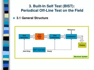
BIST architecture at IC level (general overview) Primary inputs Access to BIST functions TP generation and application BIST controller Internal circuit under test Response capture / evaluation Primary outputs
BIST: TP generation and application - main problems • External generation of TPs to be stored in ROM: silicon area • Exhaustive / pseudo-exhaustive (when circuit partitioning is done previously) test: complexity of partitioning, test application time • Pseudo-random test pattern generation: fault simulation required (but the silicon area and design effort are small)
BIST: response capture / evaluation - main problems • Responses stored in ROM and compared vector by vector: the required silicon area is again the main problem • Response compaction (several alternatives are available: transition counting, 1s counting, signature analysis, etc.): aliasing is possible (but the resources required and the test application time are far smaller)
The BIST controller • The BIST controller is responsible for scheduling the several phases that comprise the execution of BIST (according to the type of circuit under test) and the operations that take place in each phase • This block constitutes the interface between external test resources and the BIST functions and plays an important role in the definition of the overall system BIST strategy
BIST of combinational circuits • Any of the techniques previously referred may be used (be it for TP generation / application or for response capture / evaluation) • Pseudo-random TP generation and response compaction by signature analysis are common BIST solutions for this type of circuits
Combinational circuits: TP generation / application • Pseudo-random TP generation via an LFSR (Linear Feedback Shift Register) for a 2:1 multiplexer
Combinational circuits: TP generation / application • Recommended exercises: • What connections should be made between the circuit under test and the LFSR? • What is the required number of test clock cycles? • What should be the initial value in the LFSR outputs (Q0 to Q3)? • Would it be possible to use a 3-bit LFSR? • How do the pseudo-random and exhaustive TP generation alternatives compare in terms of test overhead?
Combinational circuits: response capture / evaluation • Response compaction (by signature analysis) via an LFSR for the 2:1 multiplexer
Combinational circuits: response capture / evaluation • Recommended exercises : • What connections should be made between the circuit under test and the LFSR? • What is the required number of test clock cycles? • What should be the initial value in the LFSR outputs? • Will the number of bits in the signature influence the probability of aliasing? • Present an example showing the aliasing effect
Combinational circuits: response capture / evaluation • Other compaction alternatives: • Transition counting • Syndrome counting (number of 1s) • Recommended exercise: considering that an exhaustive test is applied to the 2:1 multiplexer, determine the expected result for the three alternatives referred. In which case will the probability of aliasing be higher?
BIST of sequential circuits • With the exception of deterministic testing, using TPs stored in ROM, the remaining techniques presented for TP generation / application (exhaustive or pseudo-exhaustive, pseudo-random TP generation) are not applicable with sequential circuits • Will response compaction, by the methods presented (e.g. signature analysis), be applicable in this case?
BIST of sequential circuits • The design for testability techniques commonly used (namely scan design) eliminate the sequential nature of the circuit and enable the usage of the BIST methods considered previously • The memory elements (FF) may in fact integrate the structures implementing pseudo-random TP generation and response compaction via signature analysis
BIST of macro-cells • This hierarchical level helps to solve the test problems associated with complex blocks available to ASIC designers • Each macro-cell comprises its own BIST resources, according to the methods already described, which now have to be integrated into the overall BIST strategy defined for the upper hierarchical levels
BIST of low / medium complexity macro-cells • Low / medium complexity macro-cells, such as memory blocks, require relatively homogeneous BIST resources: • BIST of ROM blocks may be done by reading each memory address and compacting its contents into a signature • RAM blocks are medium complexity macro-cells and their BIST functions take into account several fault models
BIST of higher complexity macro-cells • The availability of higher complexity macro-cells (e.g. a microcontroller), integrating different circuit blocks, calls for a standard interface facilitating access to the BIST functions present • The heterogeneous nature of these BIST functions and the need to protect intellectual property rights led to the development of an IEEE standard in this area
BIST of mega-cells: the IEEE P1500 proposed standard • The IEEE P1500 proposes a standard • Addressing ICs “containing embedded cores, i.e. reusable mega-cells” • “Independent of the underlying functionality of the IC or its individual embedded cores” • Creating the “testability requirements for detection and diagnosis (...), while allowing for ease of inter-operability of cores originated from distinct sources” • “Usable for all classes of digital cores including hierarchical ones”
Interface between BIST and the BST infrastructure • The BST infrastructure facilitates access to the BIST functions present in an IC, since: • The TAP provides access to the BIST controller, which no longer requires dedicated test pins • The IEEE 1149.1 standard defines an optional instruction called RUNBIST, which standardises access to the BIST functions present, independently of the manufacturer and functionality of the circuit
Architecture of a BST component with BIST • The BIST controller at IC level uses the BIST bus to interface the BST infrastructure and the BIST structures present
Architecture of a BST component with BIST • The BIST controller is necessary to schedule the operation of the BIST functions present • The BST register can also be used for TP generation / application and response capture / evaluation, e.g. for pseudo-random TP generation and response compaction by signature analysis (using modified BS cells)
The RUNBIST instruction revisited • The main specifications of the IEEE 1149.1 standard in relation to RUNBIST are as follows: • Self-test modes of operation shall execute only when the TAP controller is in the Run Test / Idle state • A duration shall be specified for the self-test (number of test clock cycles) • The test data register selected by RUNBIST shall contain the self-test result after the specified number of test clock cycles were applied • ...
The RUNBIST instruction revisited • As a simple application example, the reader is invited to design the BIST structures for a BST component containing the 2:1 multiplexer previously considered • Suggestion: reuse the BS cells to implement the structures required for pseudo-random TP generation and response compaction by signature analysis
Hierarchical BIST • BST components supporting BIST facilitate the implementation of a hierarchical BIST strategy • The printed circuit board should in this case contain a BIST controller (a dedicated component for this purpose), which will be responsible for the implementation of the test protocol presented for BST boards (infrastructure test, interconnection test, component test)
Hierarchical BIST • The existence of a BST infrastructure in the board test controller enables the implementation of a hierarchical self-test strategy in which the IEEE 1149.1 standard is used both at board and system level • However, and since BST was developed to facilitate the structural testing of digital printed circuit boards, its extension to system level faces some restrictions (mention one)
Hierarchical BIST: IEEE 1149.5 and IEEE P1500 • IEEE 1149.5 (Standard for Test and Maintenance Bus) defines a system level test bus comprising 4+1 lines (MMD, MSD, MCTL, MCLK, MPR) • There are also other solutions proposed with the objective of enabling the use of the IEEE 1149.1 standard at system level, with the advantage of optimising the test resources required
Design for testability and BIST in the Pentium Pro processor • A suitable trade-off solution has to be found, concerning the percentage of silicon area dedicated to testability and BIST functions • Design for testability can not be excluded, but we must keep in mind that the silicon area used for this purpose could instead be used to improve circuit performance, therefore leading to higher probability of commercial success
Design for testability and BIST in the Pentium Pro processor • The main requirements that led to the design for testability / BIST functions present in the Pentium Pro processor were the following: • “Have zero performance impact” • “Have minimal die area impact” • “Be multiuse features wherever possible (supporting component debug, production test, and so on)” • “Be designed in from the start (that is, coded and validated in the register-transfer-level model)”
Design for testability and BIST in the Pentium Pro processor Reference: A. Carbine, D. Feltham, “Pentium Pro Processor Design for Test and Debug,” IEEE Design and Test of Computers, July-September 1999, pp. 77-82.
Design for testability and BIST in the Pentium Pro processor • The Pentium Pro BST infrastructure supports seven public instructions and “many more private instructions” to support test and debug • Scan-out provides observability of more than 2.000 internal nodes (snapshot / signature) • Debug stops the processor and enables an interactive test mode, following which the processor may return to the normal execution mode
Design for testability and BIST in the Pentium Pro processor • The Internal breakpoint mechanism can be set up for several internal events and for the subsequent debugging actions • Microcode update enables the temporary modification of microcode sections to facilitate test and debug in early silicon • The IDDQ mode uses a private BST instruction to disable all devices that draw static current and enable IDDQ tests
Design for testability and BIST in the Pentium Pro processor • Main features of the Pentium Pro BIST functions: • There is a self-test routine that is “primarily targeted at achieving high toggle coverage for burn-in testing” • LFSRs were used to implement BIST structures for “several inaccessible programmable logic arrays” • The L2 PBIST is a programmable array test pattern generator to facilitate the production test of the L2 cache memory (256 K)
Design for testability and BIST in the Pentium Pro processor • Production test effectiveness is ultimately measured by the number of defective components that are shipped to customers (in parts per million) and not by fault coverage figures • Design for testability and BIST in the Pentium Pro required 4% of the CPU silicon area and 6% of the L2 cache memory area, with “no negative impact on processor performance, either in clock frequency or instructions per clock”