Download
1 / 28

E N D
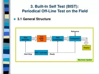
1. Copyright 2005, Agrawal & Bushnell BIST 1 Definition of BIST
Pattern generator
LFSR
Response analyzer
MISR
Aliasing probability
BIST architectures
Test per scan
Test per clock
Circular self-test
Memory BIST
Summary
2. Copyright 2005, Agrawal & Bushnell BIST 2
3. Copyright 2005, Agrawal & Bushnell BIST 3 Pattern Generator (PG) RAM or ROM with stored deterministic patterns
Counter
Pseudorandom pattern generator
Feedback shift register
Cellular automata
4. Copyright 2005, Agrawal & Bushnell BIST 4 Pseudorandom Integers
5. Copyright 2005, Agrawal & Bushnell BIST 5 Pseudo-Random Pattern Generation Standard Linear Feedback Shift Register (LFSR)
Produces patterns algorithmically � repeatable
Has most of desirable random # properties
May not cover all 2n input combinations
Long sequences needed for good fault coverage
6. Copyright 2005, Agrawal & Bushnell BIST 6 Matrix Equation for Standard LFSR 0
0
.
.
.
0
0
1
7. Copyright 2005, Agrawal & Bushnell BIST 7 LFSR Implements a Galois Field Galois field (mathematical system):
Multiplication by X same as right shift of LFSR
Addition operator is XOR ( )
Ts companion matrix:
1st column 0, except nth element which is always 1 (X0 always feeds back)
Rest of row n � feedback coefficients hi
Remaining identity matrix means a right shift
Near-exhaustive (maximal length) LFSR
Cycles through 2n � 1 states (excluding all-0)
8. Copyright 2005, Agrawal & Bushnell BIST 8 LFSR Properties Must not initialize to all 0�s � hangs
If X is initial state, LFSR progresses through states
X, Ts X, Ts2 X, Ts3 X, �
Matrix period:
Smallest k such that Tsk = I
k = LFSR cycle length
Maximum length k = 2n-1, when feedback (characteristic) polynomial is primitive
Example: 1 + X+ X3
Characteristic polynomial:
1 + h1 x + h2 X2 + � + hn-1 Xn-1 + Xn
9. Copyright 2005, Agrawal & Bushnell BIST 9 LFSR: 1 + X + X3
10. Copyright 2005, Agrawal & Bushnell BIST 10 LFSR as Response Analyzer Use cyclic redundancy check code (CRCC) generator (LFSR) for response compacter
Treat data bits from circuit POs to be compacted as a decreasing order coefficient polynomial
CRCC divides the PO polynomial by its characteristic polynomial
Leaves remainder of division in LFSR
Must initialize LFSR to seed value (usually 0) before testing
After testing � compare signature in LFSR to precomputed signature of fault-free circuit
11. Copyright 2005, Agrawal & Bushnell BIST 11 Example Modular LFSR Response Analyzer LFSR seed is �00000�
12. Copyright 2005, Agrawal & Bushnell BIST 12 Signature by Logic Simulation
13. Copyright 2005, Agrawal & Bushnell BIST 13 Signature by Polynomial Division X5 + X3 + X + 1
Char. polynomial
14. Copyright 2005, Agrawal & Bushnell BIST 14 Multiple-Input Signature Register (MISR) Problem with ordinary LFSR response compacter:
Too much hardware if one of these is put on each primary output (PO)
Solution: MISR � compacts all outputs into one LFSR
Works because LFSR is linear � obeys superposition principle
Superimpose all responses in one LFSR � final remainder is XOR sum of remainders of polynomial divisions of each PO by the characteristic polynomial
15. Copyright 2005, Agrawal & Bushnell BIST 15 Modular MISR Example
16. Copyright 2005, Agrawal & Bushnell BIST 16 Aliasing Probability Aliasing means that faulty signature matches fault-free signature
Aliasing probability ~ 2-n
where n = length of signature register
Example 1: n = 4, Aliasing probability = 6.25%
Example 2: n = 8, Aliasing probability = 0.39%
Example 3: n = 16, Aliasing probability = 0.0015%
17. Copyright 2005, Agrawal & Bushnell BIST 17 BIST Architectures Test per scan
Test per clock
Circular self-test
Memory BIST
18. Copyright 2005, Agrawal & Bushnell BIST 18 Test Per Scan BIST
19. Copyright 2005, Agrawal & Bushnell BIST 19 Test per Clock BIST New fault set tested every clock period
Shortest possible pattern length
10 million BIST vectors, 200 MHz test / clock
Test Time = 10,000,000 / 200 x 106 = 0.05 s
Shorter fault simulation time than test / scan
20. Copyright 2005, Agrawal & Bushnell BIST 20 Circular Self Test
21. Copyright 2005, Agrawal & Bushnell BIST 21 Built-in Logic Block Observer (BILBO) Combined functionality of D flip-flop, pattern generator, response analyzer, and scan chain
Reset all FFs to 0 by scanning in zeros
22. Copyright 2005, Agrawal & Bushnell BIST 22 Test per Clock with BILBO SI � Scan In
SO � Scan Out
Characteristic polynomial: 1 + x + � + xn
CUTs A and C: BILBO1 is MISR, BILBO2 is LFSR
CUT B: BILBO1 is LFSR, BILBO2 is MISR
23. Copyright 2005, Agrawal & Bushnell BIST 23 BILBO Serial Scan Mode B1 B2 = �00�
Dark lines show enabled data paths
24. Copyright 2005, Agrawal & Bushnell BIST 24 BILBO LFSR Pattern Generator Mode B1 B2 = �01�
25. Copyright 2005, Agrawal & Bushnell BIST 25 BILBO in DFF (Normal) Mode B1 B2 = �10�
26. Copyright 2005, Agrawal & Bushnell BIST 26 BILBO in MISR Mode B1 B2 = �11�
27. Copyright 2005, Agrawal & Bushnell BIST 27 Memory BIST
28. Copyright 2005, Agrawal & Bushnell BIST 28 Summary LFSR pattern generator and MISR response analyzer � preferred BIST methods
BIST has overheads: test controller, extra circuit delay, primary input MUX, pattern generator, response compacter, DFT to initialize circuit and test the test hardware
BIST benefits:
At-speed testing for delay and stuck-at faults
Drastic ATE cost reduction
Field test capability
Faster diagnosis during system test
Less effort to design testing process
Shorter test application times