Download
1 / 51
540 likes | 1.14k Views
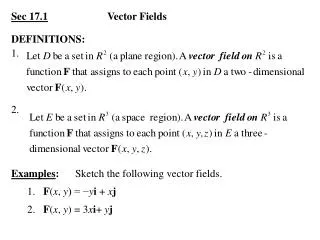
Imaging Vector Fields Using Line Integral Convolution. Presented by Farial Shahnaz. Line Integral Convolution (LIC) :. LIC represents a new and general method for imaging two and three dimensional vector fields. The LIC Algorithm takes as input - An input image

E N D
Imaging Vector Fields Using Line Integral Convolution Presented by Farial Shahnaz
Line Integral Convolution (LIC): LIC represents a new and general method for imaging two and three dimensional vector fields. The LIC Algorithm takes as input - • An input image • A vector field and generates an output image by filtering the input image along local stream lines defined by the vector field .
Imaging Vector Fields:Even though imaging vector fields appear to have a limited application ( primarily scientific visualization) , algorithms that can image such directional information have wide application across both scientific and artistic domains.
Desired Properties for Vector Field Imaging Algorithms: • Accuracy • Locality of calculation • Simplicity • Controllability • Generality
Spatial Resolution: This includes sampling the vector field with streamlines or particle traces, and using icons.
Streamlines: Streamlines in 3D Streamlines in 2D
Disadvantage - Loss of Accuracy: Depends critically on the placement of streamers or particle sources, and depending on their placement, currents on the data field can be missed.
Disadvantage – Loss of controllability: Use up a considerable amount of spatial resolution, which limits their use to small vector fields.
Generating textures with the use of a Vector field : This uses a vector field to control the generation of band limited noises. E.g.Van Wijk’s “Spot Noise” algorithm
Disadvantage – Loss of Generality: This approach, by definition, depends heavily on the form of the texture (spot noise) itself. Specifically, it does not easily generalize to other forms of textures that might be better suited to a particular class of vector data.
This approach is a generalization of traditional line drawing techniques and the spatial convolution algorithms given by Van Wijk and Perlin. DDA Convolution:
The DDA Convolution algorithm works in the following way: • Each vector in the field is used to define a long, narrow, DDA generated filter kernel that is tangential to the vector and going in the positive and negative vector direction some fixed distance, L. • A texture is then mapped one-to-one onto the vector field. • The input texture pixels under the filter kernel are summed, normalized by the length of the filter kernel, 2L, and placed in an output pixel image for the vector position.
Images generated by the DDA convolution technique : . Simple circular vector field with Computational fluid dynamics White noise (texture) code with White noise
This algorithm is very sensitive to symmetry of the DDA algorithm and filter. If the algorithm weights the forward direction more than the backward direction, the circular field in figure 2 appear to spiral inward implying a vortical behavior that is not present in the field. Symmetry:
Disadvantage – Lack of Accuracy : • This algorithm assumes that the local vector field can be approximated by a straight line. • For complex structures smaller than the length of the DDA line, the local radius of curvature is small and is not well approximated by a straight line. • In a sense, DDA convolution renders the vector field unevenly, treating linear portions of the vector field more accurately than small scale vortices.
Line Integral Convolution(LIC):The LIC algorithm is a derivative of the DDA technique that, instead of using a vector, uses a local streamline to generate the filter. The local behavior of the vector field can be approximated by computing a local stream line that starts at the center of pixel (x, y) and moves out in the positive and negative directions.
As with the DDA algorithm, it is important to maintain symmetry about a cell. Hence, the local stream line is also advected backwards by the negative of the vector field as shown in equation (3). Symmetry: Primed variables represent the negative direction counterparts to the positive direction variables and are not repeated in subsequent definitions. As above Dsi, is always positive.
Illustration of local stream line calculation : Continuous sections of the local stream line — i.e. the straight line segments in figure 3 — can be thought of as parameterized space curves in s and the input texture pixel mapped to a cell can be treated as a continuous scalar function of x and y. It is then possible to integrate over this scalar field along each parameterized space curve.
Line Integrals of the First Kind (LIFK): Such integrals can be summed in a piecewise C1fashion and are known as line integrals of the first kind (LIFK).
Result of Applying LIFK : • This results in a variation of the DDA approach that locally follows the vector field and captures small radius of curvature features. • For each continuous segment, i, an exact integral of a convolution kernel k(w) is computed and used as a weight in the LIC as shown in the equation on the left.
: Local Streamline L : • The length of the local stream line, 2L, is • given in unit pixels. Depending on the inputpixel field, F, if L is too large, all the resulting LICs will return values very close together for all coordinates (x, y). • On the other hand, if L is too small then an insufficient amount of filtering occurs. Since the value of L dramatically affects the performance of the algorithm, the smallest effective value is desired.
Truncation of the streamline / termination of algorithm: • Singularities in the vector field occur when vectors in two adjacent local stream line cells geometrically “point” at a shared cell edge. This results in Dsivalues equal to zero leaving l in equation (6) undefined. This situation can easily be detected and the advection algorithm terminated. • If the vector field goes to zero at any point, the LIC algorithm is terminated as in the case of a field singularity. Both of these cases generate truncated stream lines.
Periodic motion filters:The LIC algorithm visualizes local vector field tangents, but not their direction. The local vector field direction can be rendered via animation of successive LIC imaged vector fields using varying phase shifted periodic filter kernels.
- The success of this technique depends on the shape of the filter. - If the filter is periodic, by changing the phase of such filters as a function of time, apparent motion in the direction of the vector field is created. - It is possible, and desirable, to create periodic low-pass filters to blur the underlying texture in the direction of the vector field. Required Properties of the filter:
A Hanning filter, 1/2(1 + cos(w+b)), has this property. It has low band-pass filter characteristics, it is periodic by definition and has a simple analytic form. This function will be referred to as the ripple filter function. Hanning Filter: .
. Ripple filter function: .
The general form of this function (Hanning ripple function * Hanning window function) is shown in the following equation : General form of the filter: . c : dilation constant of the Hanning window function d : dilation constant of the Hanning ripple function : phase shift of the ripple function given in radian
Periodicity of the Ripple function :Choosing the periodicity of the ripple function represents making a design trade-off between maintaining a nearly constant frequency response as a function of phase shift and the quality of the apparent motion.
Frequency of the filter: • A low frequency ripple function results in a windowed filter whose frequency response noticeably changes as a function of phase. This appears as a periodic blurring and sharpening of the image as the phase changes. • Higher frequency ripple functions produce windowed filters with a nearly constant frequency response. However, the feature size picked up by the ripple filter is smaller and the result is less apparent motion. • If the ripple frequency exceeds the Nyquist limit of the pixel spacing the apparent motion disappears.
Normalization:A normalization to the convolution integral is performed in equation 5 to insure that the apparent brightness and contrast of the resultant image is well behaved as a function of kernel shape, phase and length.
Variable and Constant kernel normalization: • Because the actual length of the LIC may vary from pixel to pixel, the denominator cannot be pre-computed. • However, an interesting effect is observed if a fixed normalization is used. Truncated stream lines are attenuated which highlights singularities.
fluid dynamics vector field imaged with variable and constant kernel normalization: Variable kernel normalization Constant kernel normalization
White noise convolved with checkerboard vector field: fixed normalizationgradient shaded normalization
THREE-DIMENSIONAL LIC: • The LIC algorithm easily generalizes to higher dimensions. • In the 3D case, cell edges are replaced with cell faces. Both the input vector field and input texture must be three-dimensional. • The output of the three-dimensional LIC algorithm is a 3D image or scalar field.
3D rendering: This is a 3D rendering of an electrostatic field with two point charges placed a fixed distance apart from one another.
Implementation of the LIC algorithm:The LIC algorithm is designed as a function, which maps an input vector field and texture to a filtered version of the input texture. The dimension of the output texture is that of the vector field. Careful attention must be paid to the size of the input texture relative to that of the vector field.
Size of the input texture: • If the texture is too large it is cropped to the vector field dimensions. • If the input texture is smaller than the vector field the implementation of the algorithm wraps the texture using a toroidal topology. That is, the right and left edges wrap as do the top and bottom edges. • If too small a texture is used, the periodicity induced by the texture tiling will be visible.
Performance ( in cells/sec): • DDA(2D): 30,000CPS • LIC (2D): 3,000CPS • LIC (3D):1,200 CPS (Tests were run on an unloaded IBM 550 RISC 6000)
Application :The LIC implementation is a module in a data flow system like that found in a number of public domain and commercial products. This implementation allows for rapid exploration of various combinations of operators. The algorithm can be used as a data operator in conjunction with other operators. Specifically, both the texture and the vector field can be preprocessed and combined with post processing on the output image.
Post processing:The output of the LIC algorithm can be operated on in a variety of ways. In this section several standard techniques are used in combination with LIC to produce novel results.
The fixed normalization fluid dynamics field is multiplied by a color image of the magnitude of the vector field. .
A wind velocity visualization is created by compositing an image of North America under an image of the velocity field rendered using variable length LIC over 1/f noise.
The LIC algorithm can be used to process an image using a vector field generated from the image itself