Download
1 / 27
401 likes | 1.04k Views
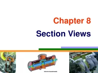
Drawing Section Views. What is a “Section View” ?. A section view is a view used on a drawing to show an area or hidden part of an object by cutting away or removing some of that object. The cut line is called a “cutting plane”, and can be done in several ways.

E N D
What is a “Section View” ? • A section view is a view used on a drawing to show an area or hidden part of an object by cutting away or removing some of that object. • The cut line is called a “cutting plane”, and can be done in several ways. • The following slides will help show the several methods or types of “section views”
Visualizing the Cutting Plane • It is very important to Visualize what the part will look like after it is cut open. • Choosing the type of section and location of the cutting plane. • Making the cut and drawing the view in the proper location.
Full Section • In a full section, the cutting plane line passes fully through the part. • Normally a view is replaced with the full section view. • The section-lined areas are those portions that have been in actual contact with the cutting-plane.
Half Section • Half Section is used to the exterior and interior of the part in the same view. • The cutting-plane line cuts halfway through the part and removes one quarter of the material. • The line that separates the different types (interior and exterior) may be a centerline or a visible line.
Section Lining • Materials – Common materials • The symbol for cast iron can be used for most section views. • Refer to any common drafting text for additional symbols.
Section Lining • 45 degree angle lines should be used. • 1/8” between lines. • All lines should be uniformly spaced • Thin sections may be blackened in completely • Spacing lines by eye increases speed
Section Lining – Line Placement • Lines should never be parallel or perpendicular to the object lines. • If the outline of the object has 45 degree lines, 30 or 60 degree lines should be used. • Assemblies with several parts should be lined with varying angle section lines.
Offset Sections • Used to show parts and features that do not line up with each other. • Cutting-plane line does not travel in a straight line. • The offsets or bends in the cutting-plane line do not show in the section. • The versatility of this section makes it very useful.
Aligned Sections • Usually used on symmetrical circular parts. • Place the cutting-plane line to show the most detail. • All parts and details are rotated into the section view. • Ribs and spokes can be left un-lined for better clarity in the section view.
Revolved Sections • Used to show a small portion of a drawing. • Show a cross-section of an area turned 90 degrees or perpendicular to the object. • Put into a drawing to show an area not normally shown.
Broken-out Sections • Used to generate a section for a small area without using a cutting-plane line. • Removes a small amount of material to show the interior details. • Always used in an orthographic view. • Used to enhance the orthographic view by giving the viewer a better look at key interior details.
Sectioning Shafts • Used to show a break in a longer part allowing better used of drawing surface. • Gives the impression of a 3-D break on the shaft. • Adds a touch of flair to the drawing.
Assembly Sections • Shows how parts fit together • Allows better clarity with a complicated assembly of parts. • Shows how parts not only fit together, but allows for a visual view of how they function.
Bibliography • Technical Drawing, Eleventh Edition; Giesecke, Mitchell, Spencer, Hill, Dygdon, Novak; Prentice Hall, Upper Saddle River, NJ 07458; ISBN 0-13-022569-X • Giesecke, Frederick E; Mitchell, Alva; Spencer, Henry C.; Hill, Ivan Leroy; Dygdon, John T.; Novak, James E., TECHNICAL DRAWING, 11th Edition, @2000. Electronically reproduced by permission of Pearson Education, Inc., Upper Saddle River, New Jersey. • Engineering-Technical Drafting and Graphics; J.W. Giachino, Henry J. Beukema; American Technical Society, Chicago, Illinois - Second Edition