Download
1 / 25
250 likes | 518 Views
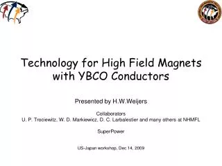
Better conductors for 16-20 T dipoles?. David Larbalestier Applied Superconductivity Center, National High Magnetic Field Laboratory, Florida State University, Tallahassee FL USA

E N D
Better conductors for 16-20 T dipoles? David Larbalestier Applied Superconductivity Center, National High Magnetic Field Laboratory, Florida State University, Tallahassee FL USA (special thanks to Lance Cooley (FNAL), Dan Dietderich (LBNL), Arno Godeke (LBNL) , Peter Lee (ASC), Mark Rikel (Nexans), Venkat Selvamanickam (TcSUH), Mike Sumption (OSU), Chiara Tarantini (ASC), and Aixia Xu (TcSUH) for input for this talk) (And Bruce Strauss for yesterday’s talk) Future Circular Collider Workshop UniMail, University of Geneva, Geneva Switzerland February 12-14, 2014 Supported by DOE-HEP, NSF, State of Florida and CERN
Key points – work required! • Three possible conductors (5 years) • New and very much improved Nb3Sn • Further developed round wire Bi-2212 • Cable-friendly REBCO coated conductors • Three long shots (10 years) • Round wire REBCO (2212 analog) • Round wire Fe-base superconductor • MgB2 with in-grain scattering for high vortex pinning and Hc2 enhancement
2 mm Ag 1 mm HTS ~ 30 nm LMO ~ 30 nm Homo-epi MgO 20mm Cu ~ 10 nm IBAD MgO < 0.1 mm 50mm Hastelloy substrate 20mm Cu Magnet Conductors so far…. 1. Nb47Ti conductor- thousands of 8 mm diameter Nb47Ti filaments in pure Cu (0.8 mm dia.), easily cabled to operate at 10-100 kA 3. REBCO coated conductor – extreme texture (single crystal by the mile) – for maximum GB transparency 4. Bi-2212 – high Jc without macroscopic texture! 2. Bi-2223 – the first HTS conductor – uniaxial texture developed by deformation and reaction
Isotropic, multifilament 2212 has higher conductor Jcthan coated conductor! Requires ~100 bar 890°C processing High Jc, high Je and high Jw has been demonstrated in a coil already (2.4T in 31T) Much less field distortion from 2212 than from coated conductors – better for high homogeneity coils 7 times increase in long length Je by removing bubbles ~1900 A/mm2 in 2212 + 2212 (25% sc) REBCO coated conductor (1% sc)
Accelerator use demands strong vortex pinning forces (Fp = Jc x B) • Depinning from a discrete normal (N) or insulating (I) pin is better than shear along a continuous channel (e.g. GB) which must be at least a weak superconductor (S or S’) to transmit supercurrent • I pins are better than N or S’ pins because the pinning energy scale is then the full condensation energy • High Hc2 or irreversibility field Hirr tilts the pinning force curve to high field • A high density of strong pins pushes to full summation of individual pinning forces (fp) so that Fp ~ n fp Meingast, Lee and DCL, J. Appl. Phys. 66, 5971
e 20 f Fi n e r and mor e dens el y pac k ed pr ec ip ita t es 18 e = 5 . 3 f 16 e = 4 . 4 f 14 e 3 12 = 3 . 4 N/m ) f 10 (G p e = 2 . 5 F 8 f 6 4 e = 1 . 1 f 2 0 2 3 5 7 8 9 10 0 1 4 6 11 B (T) Nb-Ti optimizes both fp so that Fp ~ n. fp • Without a-Ti precipitates, only weak GB pinning occurs • a-Ti precipitates start as normal metal (N) pins but become weakly superconducting (S’) when optimized because their high density outweighs their declining pinning strength • At optimum, a-Ti pin density n is several times vortex density
What does Nb3Sn need? • Nb3Sn has sparse and weak vortex pinning by grain boundaries that allows flux sliding along the whole GB network • What can be done? • Strengthen pinning by increasing the superfluid density (Tarantini ASC-NHMFL) • Adding point pins (Dietderich LBNL) • Restricting grain growth (Sumption OSU)
GB pins- 30-50 times lower pin density than Nb-Ti RRP A15 % of non-Cu Grain size / GB density A15 layer Jc QGB=Fp/SGB 620°C / 192h SEM Fractographs Peter Lee’s SEM images in Tarantini et al. arXiv 1310.6729, to appear SuST 2014
Jc(16T) can be enhanced by HT reaction (RRP 54/61) – but not to 2000 A/mm2 Jc (12T) is dominated by small grain size even though HT at lower temperature leaves lots of low-Sn, low Hc2 A15 present. Higher T HT helps Hc2, even as it causes grain growth From VSM data Jc(16T) first increases at medium-high temperature (680-695°C) before dropping at 750°C, even as the diffusion barriers break badly and leak large amounts of Sn Strauss (FCC talk Thursday) – we want 2000 A/mm2 at 15 T
Vortex pinning strength, QGB(16T) is strongly enhanced by high HT temp. The unit pinning force exerted by GBs on vortices increases as HT increases Pinning energy scale is Tc distribution +35% From VSM data +68% Higher T reactions require better diffusion barriers (RRP 54/61)
The minimum to be done for high Jc (16T) • Raise Hirr by pumping in as much Sn as possible • Raises the superfluid density f(Tc) and the energy scale for fp Strengthen barriers – RRR degrades for only 1-2% of barrier breakdown
Or, add insulating pins to get a full condensation energy pinning • Fine grains (~50 nm with insulating (I) Al2O3 pins) drives high Jc and Fp curve into Nb-Ti form • The problem: these are thin films and so far ppts. in FM conductors have been elusive • 2000 A/mm2 at 16 T is clearly within reach
Nb3Sn Conductors with Grain size reduction and Fp,max shift Xu, Sumption, Peng, Collings Appl. Phys. Letts submitted What (Aim)?: Toincrease Jc at 15 T, 4 K in Nb3Sn, increase Bc2, or increase flux pinning. Here we focus on pinning, by; (1) Fp, or (2) a shift of Fp,max from 0.2 Birr to 0.3 to 0.5 Birr. We will use Grain size refinement. Why?: If the Nb3Sn grain size (in films) is refined to 15-30 nm, the peak of the Fp-B curve is shifted to 0.5Birr, improving the 12 T Jc by a factor of three [D. R. Dietderich and A. Godeke, Cryogenics 48, 331 (2008)] (b) (a) A ZrO2 particle How?: Grain size ↓ by HT Temp ↓ have hit the limit (further T ↓reduces Sn %). But Rumaner [Metall. Mater. Trans. A 25, 213 (1994)] used internally oxidized Zr to reduce grain size in films. Zeitlinattempted to transfer to strands [IEEE Trans. Appl. Supercon. 15, 3393 (2005)], using internally oxidized Nb-Zr but did not see refinement. (1) We exposed Nb-Zr/Sn wires (no Cu) to Ar-Oxygen atmosphere during HT to internally oxidize Zr and refine Nb3Sn grains – with success! 45 nm Nb3Sn grain size Average Nb3Sn grain size as a function of reaction temperature Fracture SEM images of samples reacted at 850 °C for 10 min in (a) pure Ar and (b) Ar-O2 atmospheres. TEM image showing the ZrO2 particles This work was funded by the US Department of Energy, Division of High Energy Physics, Grant No. DE-FG02-95ER40900, and DE-SC0010312.
Halved grain size (45 nm) shifts Fp and provides relative Jc advantage (a) (b) (2) Next Step, Subelement with internal oxidation: based on a review of the Ellingham Diagram, we put SnO2 powder between the Cu/Sn core and the Nb-1Zr tube wall: For comparison, an analog with NbO2was also fabricated. Nb-1Zr tube The (a) Fp-B, and (b) reduced Fp-B curves of samples reacted at 650 °C for 150 h (note Birr normalized Fp curve at right indicates peak shift, distinct from Birr shift) Cu matrix SEM image of the wire with SnO2, ready to stack into multi-filament strands. Ellingham Diagram The Fp-B curves with SnO2 and NbO2 peak at ~0.3Birr and ~0.2Birr, respectively. SnO2 powder • 12 T layer Jc of the wire with SnO2 is ~6.1 kA/mm2, that for Nb2O strand 5.4 kA/mm2 – both excellent, but in fact suppressed by low Birr (20.5 T), because they are binary. • However, a ternary version should have a Birr of ~25 T, if so, we estimate that the 12 T layer Jcshould be significantly higher (perhaps ~10kA/mm2). Cu (a) (b) 10 μm Sn core Grain sizes of samples with (a) NbO2 and (b) SnO2, reacted at 650 °C for 150 h, are 91 and 43 nm, respectively. Conclusion: in light of the results obtained, we anticipate that this approach could lead to substantial improvement in the performance of Nb3Sn conductors – and is ready for ternary multifilament investigation Paper submitted to Applied Physics Letters
If Nb3Sn is plan A for a 100 TeV LHC…………. • Present RRP and PIT designs are unlikely to satisfy – the lessons they teach are that higher T reactions with more homogeneous Sn can raise Jc but that stronger diffusion barriers are essential – max Jc may be 1200 A/mm2 • Insulating pins and finer grains may get the required Jc – layer Jc of ~5000 A/mm2 (non-Cu ~ half this) shown in thin films • Fabrication of ppt-containing fine filaments has been attempted by Supergenics, SupraMagnetics and most recently Hypertech-OSU …………….a focused program will be needed to establish feasibility of a 16 T Nb3Sn conductor
Plan B: 20 T requires HTS conductors Je≈ 600 A/mm2 Note that this is 600 A/mm2 (20T) in a conductor that is about 25% 2212, so layer Jc is ~1800 A/mm2 DCL et al. Nature Materials accepted, arXiv 1305.1269 20+ T 16T 10 T REBCO tapes developed for electric utility applications (several hundred millions) versus recent HEP-driven development (so far about $5M) for Bi-2212
Can Jc of round wire (RW) 2212 go higher? Almost certainly………. Round wire Bi-2212 J. Jiang “Overpressure processing as the route to high Jc in coil length Bi-2212 round wires” MT-23 July 14-20, Boston MA, USA (2013) • Overpressure processing removes gas bubbles but leaves high angle GBs in place • However no hysteretic signature of weak links as is quite obvious in Bi-2223 • Bi-2212 phase field is broad, opening up cation defect pinning • Recall that Bi-2212 is the first HTS conductor like an LTS conductor • twisted, multifilament, round, good normal conductor in parallel – no Diffusion Barrier needed Very different in Bi-2223 tape Bi-2212 RW is an ongoing effort of US BSCCo (Bismuth Strand and Cable Collaboration at ASC-NHMFL, BNL, FNAL and LBNL with OST and Nexans (under CERN support) and in association with EUCARD2 [Ref. **] Martin et al., IEEE Trans. Appl. Supercond., (1997)
Challenge: understand 2212 phase – complex! • Mark Rikel (Nexans) in the lead (EUCARD2 and BSCCo association)
Cables: Large magnets are better protected when operated at high current– cables! • Easy path to 2212 cables through the standard Rutherford cable Danko van der Laan REBCO cables are harder (Coated Conductor is a single filament) – but possible (IRL, KIT, CORC, twisted stack (MIT) Bi-2212 Rutherford cables (Arno Godeke LBNL) with mullite insulation sleeve REBCO coated conductor cable wound in many layers helically on a round form Cables vital for 60 T hybrid at the NHMFL, an LHC energy upgrade and a neutrino machine based on a Muon Collider at Fermilab Other variants too: e.g. Roebel cable
Plan C: REBCO vortex pinning engineering works – MOCVD on IBAD substrates compatible with e.g. Cable on Round Cores (CORC) • Strong recent developments in Selvamanickam group at TcSUH (Aixia Xu et al. MT23 presentation) • Strongly enhanced vortex pinning from 4 to 77 K in magnetic fields up to 31 T in a 15 mol% Zr-added (GdY)-Ba-Cu-O superconducting tapes - Xu, Delgado, Khatri, Liu, Selvamanickam (TcSUH) and Abraimov, Jaroszynski, Kametani and Larbalestier (ASC-NHMFL) – in final draft
The insulating vortex pins that one would love in Nb3Sn too.. • BaZrO3 and RE2O3 pins give REBCO the same Jc properties as Nb-Ti • At 77K, not 4.2K • But layer thickness is 1 mm • 3-5 mm REBCO and thinner substrates would go far to equalize JE too • Pinning force at 4.2 K now exceeds 1500 GN/m3, 75 times Nb-Ti TEM by Kametani ASC-NHMFL
JE comparisons today clearly favor RW Bi-2212 – • Fine filament twisted conductor is ideal for high homogeneity NMR and accelerator magnets From the cover of the MagSci report (DCL et al. arXiv 1305.1269 – to appear Nature Materials 2014) Bi-2212 conductor support by DOE–OHEP: an outcome of Bismuth Strand and Cable Collaboration (BSCCo)
Making common cause across many sectors is possible and desirable • http://www.nap.edu/catalog.php?record_id=18355 High Magnetic Field Science and ItsApplication in the United States: CurrentStatus and Future Directions(Halperin Chair • Met in 2012, report about to issue Report released November 2013 Note the cover image! Bi-2212 developed under OHEP support!
High Magnetic Field Science and ItsApplication in the United States: CurrentStatus and Future DirectionsThe recommendations (Halperin (Harvard) Chair • Consider regional 32 T superconducting magnets at 3-4 locations optimized for easy user access. • Establish at least 3 US 1.2 GHz NMR instruments (planned commercial) for broad access and plan for ~1.5 GHz class system development • Establish high field (~30 T) facilities at neutron and photon scattering facilities • Construct a 20 T MRI instrument (for R&D) • A 40 T all‐superconducting magnet should be designed and constructed, • A 60 T DC hybrid magnet that will capitalize on the success of the current 45 T hybrid magnet at the NHMFL‐Tallahassee should be designed and built. Very strong synergy with HEP goals (LHC energy upgrade and Muon Accelerator) for high field use – needs HTS strand AND cable development
Summary • 16-20 T magnets require conductor development • Nb3Sn is probably still plan A, but: • New conductor concepts needed • Stability margin may be too small, so pointing to HTS…… • HTS now has a round wire, multifilament, twisted, good normal metal conductor (Bi-2212) • But it requires special processing • Strength properties uncertain • All HTS have quench protection issues • Specific solutions only – need general ones • Other sectors need HTS conductors too • NMR, MRI, Photon, neutron, national magnet labs