Download
1 / 9
90 likes | 219 Views
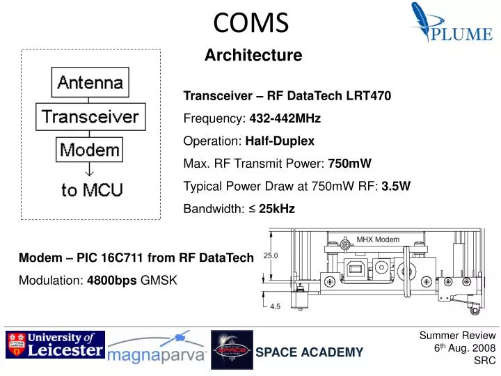
COMS. Architecture. Transceiver – RF DataTech LRT470 Frequency: 432-442MHz Operation: Half-Duplex Max. RF Transmit Power: 750mW Typical Power Draw at 750mW RF: 3.5W Bandwidth: ≤ 25kHz. Modem – PIC 16C711 from RF DataTech Modulation: 4800bps GMSK.

E N D
COMS Architecture Transceiver – RF DataTech LRT470 Frequency: 432-442MHz Operation: Half-Duplex Max. RF Transmit Power: 750mW Typical Power Draw at 750mW RF: 3.5W Bandwidth: ≤ 25kHz Modem – PIC 16C711 from RF DataTech Modulation: 4800bps GMSK Summer Review6th Aug. 2008SRC SPACE ACADEMY
Link Budget Down-Link Up-Link Ebno required =9.6 dB for a bit error rate of 10-5 [Jan_King_Calculator.xls; http://cubesat.wikidot.com/local--files/amsat-colloquium-2007/Jan_King_Calculator.xls] Modem chip from RF DataTech is a Microchip PIC. A board will be built to interface it to the transceiver and MCU. A circuit diagram has been supplied by RF DataTech. Summer Review6th Aug. 2008SRC SPACE ACADEMY
PAYLOAD Power controller From MCU HV Power supply To MCU V/I Status monitor MCP Shaping amp Discriminator Buffer To MCU Preamp Concept Incident dust particles cause plasma-induced electron cascade in single microchannel plate (MCP) with single terminal anode. Variable voltage dual output power supply – zero to 800V Charge pulse from anode goes through electronics chain, which produces a pulse-height signal to be read by the MCU Summer Review6th Aug. 2008SRC SPACE ACADEMY
Gain calculations MCA setup HV supply setup First Power-up Second power-up? 1st July 8th July 22nd July 14th July 1st August 21st 25th 6th August 24th July 17th July Electronics testing Detector assembly Vacuum pumpdown Electronics redesign Detector repair and reassembly Lab work Test plate voltage 700V Gap voltage 100V Maximum safe plate voltage 850V Summer Review6th Aug. 2008SRC SPACE ACADEMY
Flight design Approximate specifications: Detector body height = 4.3mm Mass (assuming density is similar to aluminium) = 14g Power consumption: Plate supply = 70mW Support electronics = 50mW Detector area (assuming 46mm diameter disk) = 16.6cm2 Open area = 10.5cm2 Summer Review6th Aug. 2008SRC SPACE ACADEMY
Budget Summer Review6th Aug. 2008SRC SPACE ACADEMY
Mass Budget Summer Review6th Aug. 2008SRC SPACE ACADEMY
Next Steps PSU • Fix BCR1 • Go through battery charge / discharge cycles • Select and purchase Solar Cells • Test PSU with the solar cells ADCS • Power consumption test whilst connected to the Flight Control Board • Axes sensitivity deviation test • Refining of electrical components on ADCS board • OBDH • Flight board needs to be tested • MCU needs to be programmed • Subsystems need to be physically interfaced • Subsystems need to be run from MCU PAY • Laboratory Calibrations • Heidelberg accelerator testing • Support Electronics construction • Detector body prototyping and construction Summer Review6th Aug. 2008SRC SPACE ACADEMY