Download
1 / 16
160 likes | 168 Views
This text provides an overview of number representation and conversion, CMOS logic elements, combinational and sequential logic elements and design, memory organization and implementation, clocks and timing, and finite state machines.

E N D
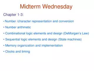
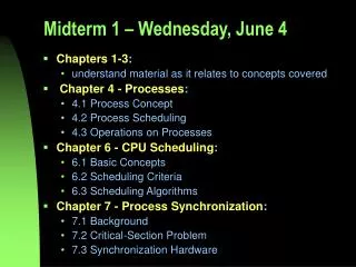
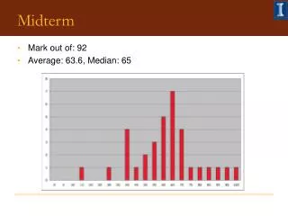
Midterm Wednesday Chapter 1-3: Number /character representation and conversion Number arithmetic CMOS logic elements Combinational logic elements and design (DeMorgan’s Law) Sequential logic elements (Flip Flops) Memory organization and implementation Clocks and timing
Overview • Finite State Machines • - Sequential circuits with inputs and outputs • State Diagrams • - An abstraction tool to visualize and analyze sequential circuits
Combinational vs. Sequential Circuits • Combinational Circuit • always gives the same output for a given set of inputs • example: adder always generates sum and carry,regardless of previous inputs • Sequential Circuit • has memory - “stores” information, • output depends on stored information (state) plus input • so a given input might produce different outputs,depending on the stored information • example: ticket counter • advances when you push the button • output depends on previous state • useful for building “memory” elements and “state machines”
4 1 8 4 30 25 5 20 10 15 Combinational vs. Sequential Logic • There are two types of “combination” locks Combinational: Success depends only onthevalues, not the order in which they are set. Sequential: Success depends onthesequenceof values (e.g, R-13, L-22, R-3).
State Machine • A type of sequential circuit • Combines combinational logic with storage • “Remembers” state, and changes output (and state) based oninputsandcurrent state State Machine Inputs Outputs Combinational Logic Circuit Storage Elements
State • The state of a system is a snapshot of all the relevant elements of the system at the moment the snapshot is taken. • Examples: • The state of a basketball game can be represented bythe scoreboard. (Number of points, time remaining, possession, etc.) • The state of a tic-tac-toe game can be represented bythe placement of X’s and O’s on the board.
State of Sequential Lock Our lock example has four different states, labelled A-D:A: The lock isnot open,and no relevant operations have been performed. B: The lock isnot open,and the user has completed the R-13 operation. C: The lock isnot open,and the user has completedR-13, followed by L-22. D: The lock isopen.
Finite State Machine • A description of a system with the following components: • A finite number of states • A finite number of external inputs • A finite number of external outputs • An explicit specification of all state transitions • An explicit specification of what determines each external output value • Often described by a state diagram. - The set of all possible states. - Inputs that trigger state transitions. - Outputs associated with each state (or with each transition).
State Diagram • Showsstates (e.g. A) andactions (e.g. B) that cause atransitionbetween states.
The Clock • Frequently, a clock circuit triggers transition fromone state to the next. • At the beginning of each clock cycle, the state machine makes a transition, based on the current state and the external inputs (Synchronous). • Not always required. In lock example, the input itself triggers a transition (Asynchronous). “1” “0” One Cycle time
Implementing a Finite State Machine • Combinational logic • Determine outputs at each state. • Determine next state. • Storage elements • Maintain state representation. State Machine Inputs Outputs Combinational Logic Circuit Storage Elements Clock
Storage • Each master-slave flipflop stores one state bit. • The number of storage elements (flipflops) neededis determined by the number of states(and the representation of each state). • Examples: • Sequential lock • Four states – two bits • Basketball scoreboard • 7 bits for each score digit, 5 bits for minutes, 6 bits for seconds,1 bit for possession arrow, 1 bit for half, …
Complete Example – Traffic Sign • Design a “blinking” traffic sign which exhibits this behavior: State 1) No lights on State 2) 1 & 2 on State 3) 1, 2, 3, & 4 on State 4) 1, 2, 3, 4, & 5 on State 1) No lights on . . ( -Repeat as long as operate switch is turned on. -The system is in state 1 when the operate switch is off) 3 4 1 5 2 DANGERMOVERIGHT
Traffic Sign State Diagram Switch on Switch off State bit S1 State bit S0 Outputs State Transitions occur on each clock cycle.
Traffic Sign Truth Tables Outputs (depend only on state: S1S0) Next State: S1’ S0’(depend on state and input) Switch Lights 1 and 2 Lights 3 and 4 Light 5 Whenever In=0, next state is 00.
Traffic Sign Combinational Logic Master-slave, or Edge Triggered D flipflops